Electrical Component Description
D386 8 SM
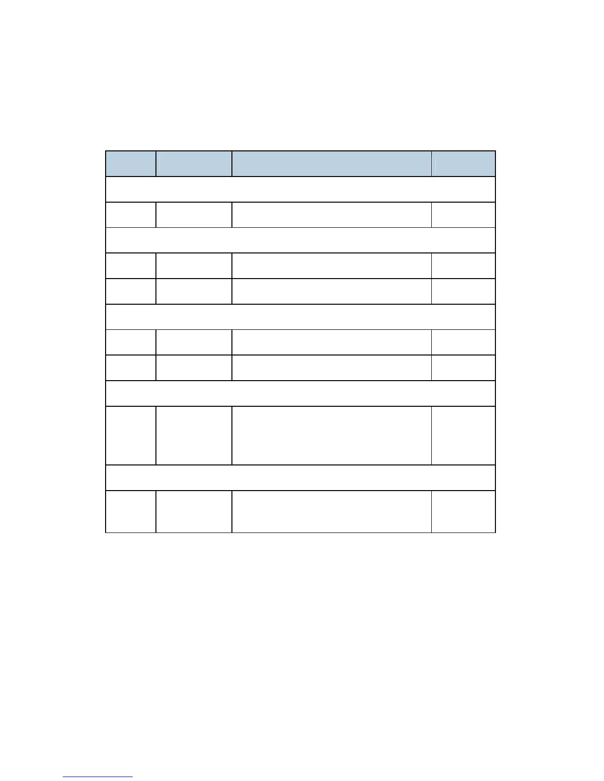
2.4 ELECTRICAL COMPONENT DESCRIPTION
Symbol Name Function Index No.
Motors
M1 Drive Motor Drives the bridge unit. 6
Sensors
S1 Tray Exit Checks for misfeeds. 4
S2 Relay Checks for misfeeds. 7
Switches
SW2 Right Guide Detects when the right guide is opened. 2
SW3 Left Guide Detects when the left guide is opened. 1
Solenoids
SOL1 Junction Gate
Moves the junction gate to direct the paper
to the upper tray (on top of the bridge unit) or
to the finisher.
3
PCBs
PCB1
Bridge Unit
Control Board
Controls the bridge unit. 5
 Loading...