Copy Adjustments
SM 4-101 D009/D011/D012/D013/D091/D092
Replacement
&
Adjustment
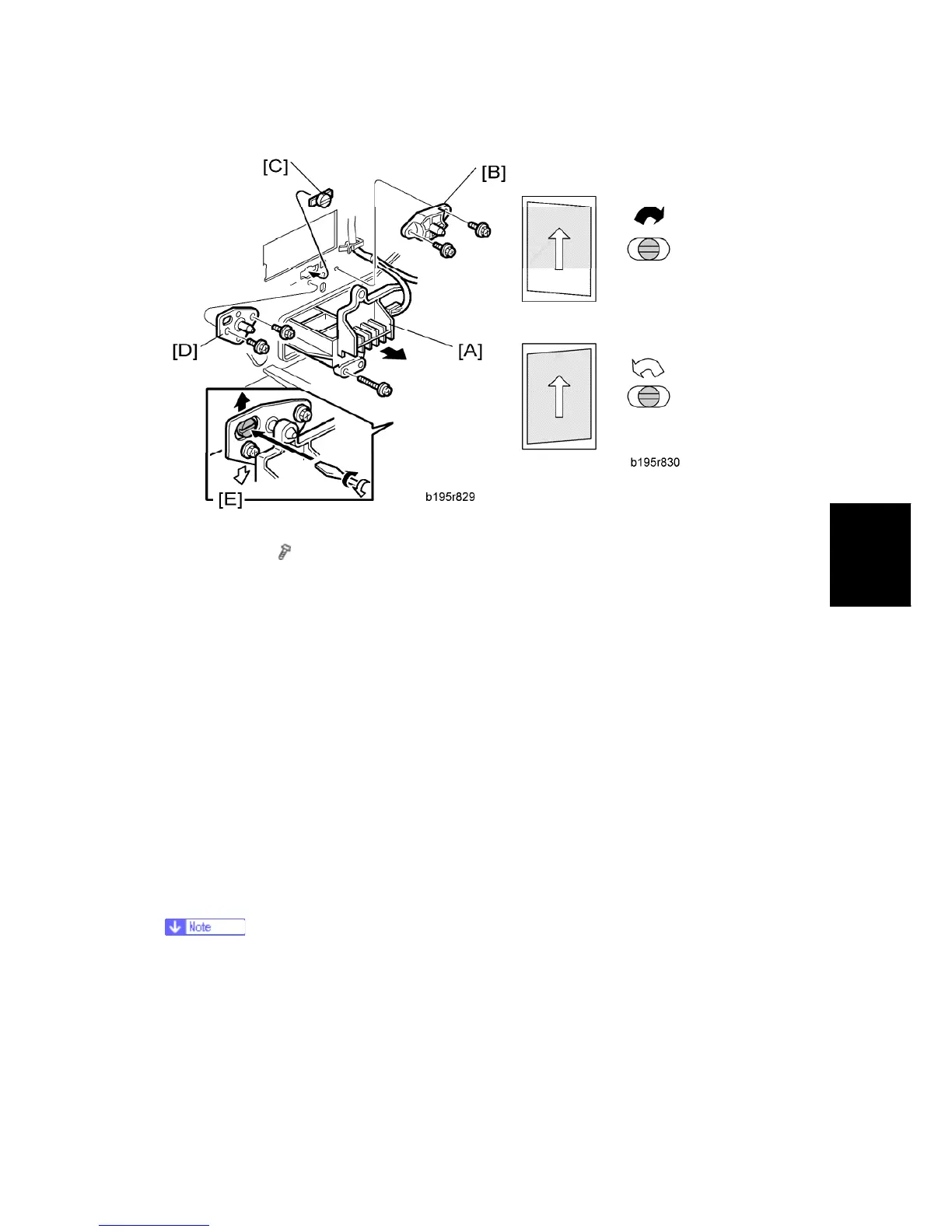
1. Laser unit [A]
2. Bracket [B] (
x2)
3. Install adjustment cam [C] (P/N: A2309003).
4. Secure positioning pin [D] (P/N A2309004) with the two screws removed with the
bracket [B]. Do not tighten the screws at this time.
5. To adjust the position of the laser unit [E]
1) Adjust the laser unit position by turning the adjustment cam. (See the illustration
above.)
2) Tighten the adjustment bracket.
3) Print the trimming area pattern to check the image. If the results are not satisfactory,
repeat steps 5-1) to 5-3).
4.17.3 SCANNING
Before doing the following scanner adjustments, perform or check the printing
registration/side-to-side adjustment and the blank margin adjustment.
Use the S5S test chart to perform the following adjustments.
 Loading...