190-01115-01 G3X™/G3X Touch™ Avionics Installation Manual
Rev. AV Page 14-3
14.4 Unit Installation
The following guidelines describe proper mechanical installation of the Garmin GMU 22 Magnetometer.
The guidelines include requirements for proper location selection in the aircraft, requirements for
supporting structure and mechanical alignment and restriction on nearby equipment.
Fabrication of a wiring harness is required. Sound mechanical and electrical methods and practices are
required for installation of the GMU 22. Refer to Section 2.3
for wiring considerations and to Section 23.8
for pinouts.
The GMU 22 is an extremely sensitive three-axis magnetic sensor. It is more sensitive to nearby magnetic
disturbances than a flux gate magnetometer. For this reason, when choosing a mounting location for the
GMU 22, see the distances from objects or devices that can disturb the magnetic field listed in Table 14-4
specifies recommended distances from magnetic disturbances for GMU 22 location.
NOTE
If the requirements listed in Table 14-4 cannot be met, a magnetometer interference test
must be performed to make sure of proper operation of the G3X system. Refer to the
AHRS/Magnetometer Installation Considerations document (190-01051-00) available
from the Garmin website (www.garmin.com
).
Make sure that any electrical conductor that comes within 10 feet (3.0 meters) of the GMU 22 is installed
as a twisted shielded pair, not a single-wire conductor. (If possible, the shield should be grounded at both
ends.)
Use nonmagnetic materials to mount the GMU 22, and replace any magnetic fasteners within 0.5 meter
with nonmagnetic equivalents (e.g. replace zinc-plated steel screws used to mount wing covers or wing tips
with nonmagnetic stainless steel screws).
In general, wing mounting of the GMU 22 magnetometer is preferred (unless as noted in Appendix B
).
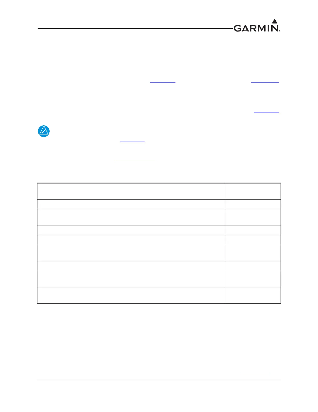
Table 14-4 Recommended Distance from Magnetic Disturbances
Disturbance Source*
Minimum Distance
from GMU 22
Electric motors and relays, including servo motors 10 feet (3.0 meters)
Ferromagnetic structure greater than 1 kg total (iron, steel, or cobalt materials,
especially landing gear structure)
8.2 feet (2.5 meters)
Ferromagnetic materials less than 1 kg total, such as control cables 3 feet (1.0 meter)
Any electrical device drawing more than 100 mA current 3 feet (1.0 meter)
Electrical conductors passing more than 100 mA current [(should be twisted
shielded pair if within 10 feet (3.0 meters)]
3 feet (1.0 meter)
Electrical devices drawing less than 100 mA current 2 feet (0.6 meter)
Magnetic measuring device other than another GMU 22 (e.g. installed flux
gates, even if unpowered)
2 feet (0.6 meter)
Electrical conductors passing less than 100 mA current [(should be twisted
shielded pair if within 10 feet (3.0 meters)]
1.3 feet (0.4 meter)
*Disturbance sources listed in table do not apply to a second installed GMU 22

 Loading...


