190-01115-01 G3X™/G3X Touch™ Avionics Installation Manual
Rev. AV Page H-119
H.4.19 ENG Configuration Page
The Engine/Airframe Input Configuration section of the Engine Configuration Page allows enabling/
disabling and customization of the engine/airframe input options that make up the EIS display and the
Engine Page on the MFD. The following sections describe configuring items listed in the Engine/Airframe
Input Configuration section of the Engine Configuration page.
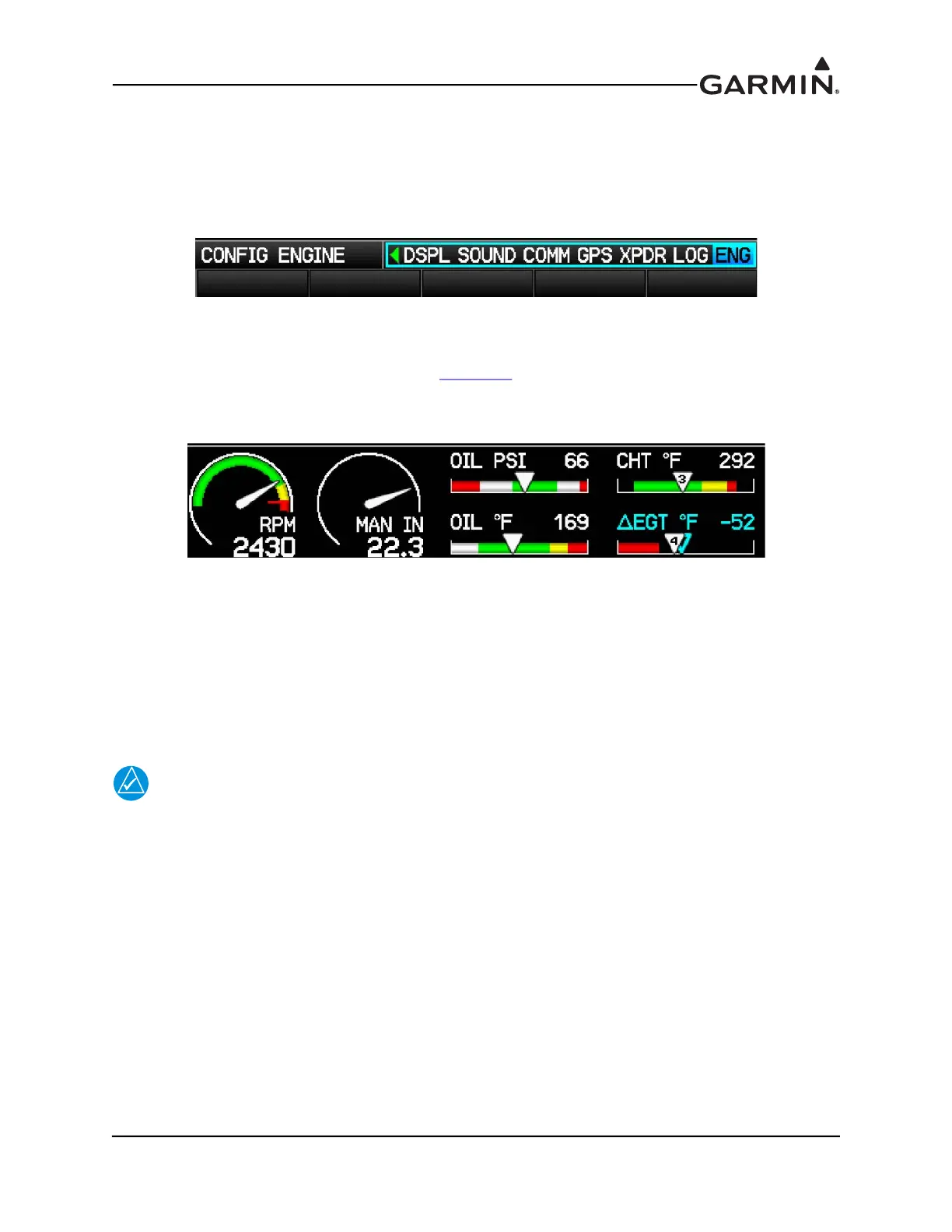
H.4.19.1 Engine/Airframe Sensors
Each of the sensors must be correctly installed (Section 21
) and configured before use. The Engine inputs
being monitored are displayed as gauges on the EIS display (Figure H-34) and also on the MFD’s Engine
Page.
Figure H-34 EIS Display (Engine Bar)
The following list of gauges, (if configured) are specifically required by FAR 91.205 and will always be
displayed on the EIS display (engine bar). Other gauges will be displayed as space permits based on a pre-
defined priority and user selections.
RPM Oil Temperature Oil Pressure Fuel Quantity
H.4.19.2 Engine Sensor Installation
NOTE
The following sections contain general guidance on engine and airframe sensor
installation. This information is provided for reference only. The installer should always
follow any installation guidance and instructions provided by the applicable engine,
sensor, or kit-plane manufacturer. Additionally, all installation practices should be done in
accordance with AC 43.13-1B.
Section 26 through Section 29 contain interface drawings for sensor installations using the Garmin sensor
kits, and for other sensor installations.

 Loading...


