190-01115-01 G3X™/G3X Touch™ Avionics Installation Manual
Rev. AV Page F-17
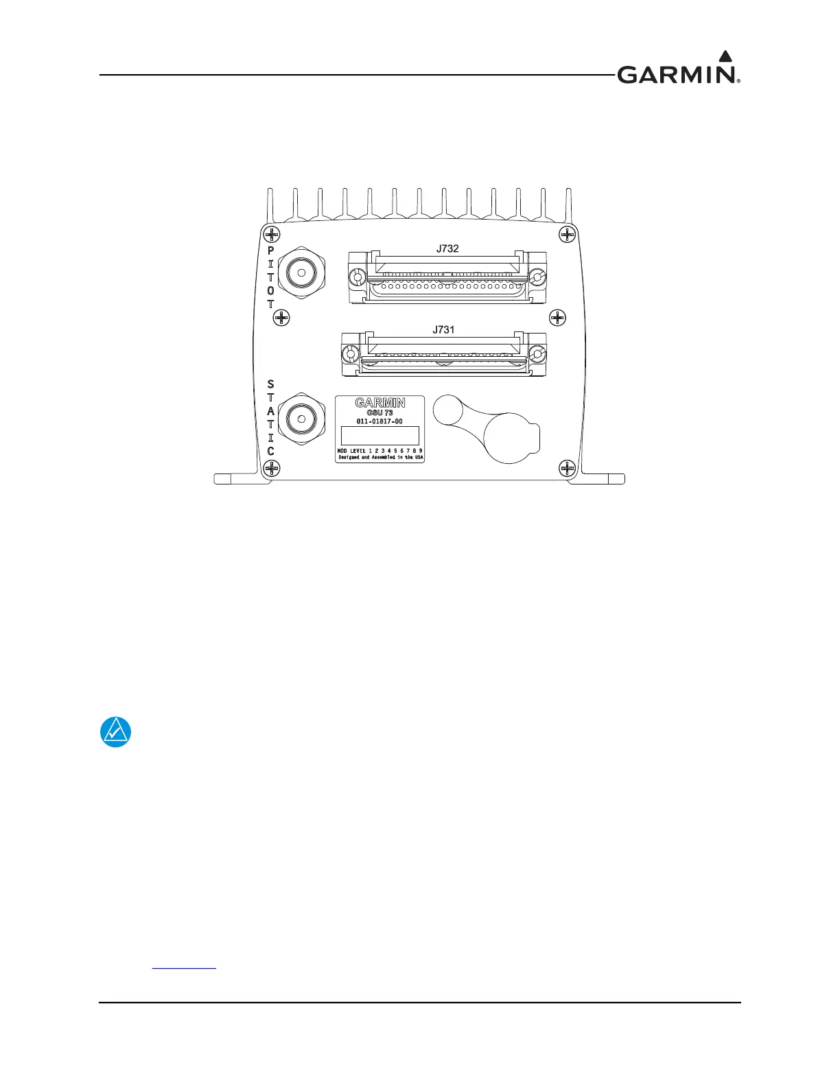
F.5.10 Pneumatic Plumbing
The GSU 73 has two ports that are connected to the aircraft’s pitot pressure source and static pressure
source. The two ports are labeled on the unit (Figure F-5). The pressure ports have 1/8-27 ANPT female
threads. The mating fitting must have 1/8-27 ANPT male threads.
Figure F-5 GSU 73 Air Hose Fitting Locations
Use appropriate air hoses and fittings to connect the pitot and static lines to the unit. Avoid sharp bends and
routing near aircraft control cables. The GSU 73 should not be at the low point of the pitot or static
plumbing lines, to avoid moisture or debris collecting at or near the unit. Make sure that no deformations
of the airframe surface have been made that would affect the relationship between static air pressure and
true ambient static air pressure for any flight condition. Refer to part 43, Appendix E for approved
practices while installing hoses and connections.
F.5.11 Pneumatic Connections
The following steps should be used to aid in the fabrication of pneumatic hose connections and in attaching
the aircraft pitot pressure source and aircraft static pressure source to the GSU 73.
NOTE
Check pneumatic connections for errors before operating the GSU 73. Incorrect plumbing
could cause internal component damage. See the following cautions when connecting
pneumatic lines.
1. Make sure the aircraft static pressure port is plumbed directly to the unit static pressure input port
and the aircraft pitot pressure port is plumbed directly to the unit pitot pressure input port.
2. Seal the threads of pneumatic fittings at the connector ports. Use caution to make sure there are no
pneumatic leaks.
3. Use care to avoid getting fluids or particles anywhere within the pitot and static lines connected to
the GSU 73.
The installer must fabricate any additional mounting equipment needed. Use outline and installation
drawing Figure F-7
for reference.

 Loading...


