190-01115-01 G3X™/G3X Touch™ Avionics Installation Manual
Rev. AV Page 21-35
21.3.11 Carburetor Temperature Sensor
21.3.11.1 Lycoming and Continental Engine Sensor Installation
The UMA 1B10R platinum resistance temperature detector (RTD) is applicable to all carbureted
Lycoming and Continental engines that accept a temperature probe with ¼-28 threads.
General Installation Guidance:
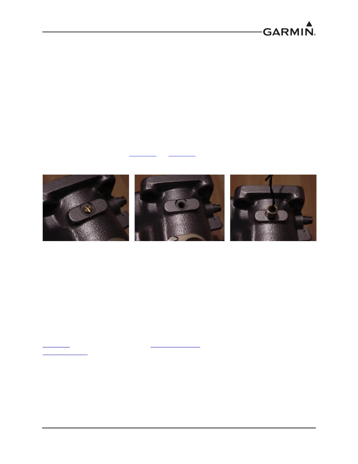
1. Locate and remove the threaded ¼-28 brass plug (Figure 21-20 and Figure 21-21) on the side of
the carburetor as shown in Figure 21-20. If a threaded plug is not present (as is the case with many
older carburetors), consult the engine and/or carburetor manufacturer for instructions on how to
drill and tap the lead plug adjacent to the butterfly valve.
2. Install a very small amount of thread lubricant on the probe threads and insert into the carburetor
(Figure 21-22).
3. Connect the supplied connector to the appropriate inputs of the GEA 24/GSU 73 as referenced in
the G3X interconnects in Section 27
and Section 28. Secure the connector and wire assembly to an
appropriate location in the engine compartment to provide strain relief.
21.3.12 Position Sensor
In general, most potentiometer-type resistive position sensors can be used with the G3X system. Typically
these sensors take the form of a 0–5k
Ω or 0–10kΩ variable resistor. Electric trim motors with integrated
position potentiometers do not require separate position sensors.
Each position sensor installation will vary widely according to the aircraft, motion being sensed, and
mechanical installation. A standalone position sensor should ideally be mounted so the full travel of the
sensor is just slightly greater than the full travel of the control surface.
Refer to the appropriate trim motor or position sensor installation manual and G3X interconnects in
Secti
on 30 for proper wiring connections. Section 34.4.19.3.2 (for GDU 37X systems) and
Secti
on 35.4.27.1 (for GDU 4XX systems) provides calibration instructions.
Figure 21-20 Carb Temp
Sensor Mounting Location
Figure 21-21 Carb Temp
Sensor Mounting Location
w/Screw Removed
Figure 21-22 Carb Temp
Sensor Installed

 Loading...


