190-01115-01 G3X™/G3X Touch™ Avionics Installation Manual
Rev. AV Page 23-59
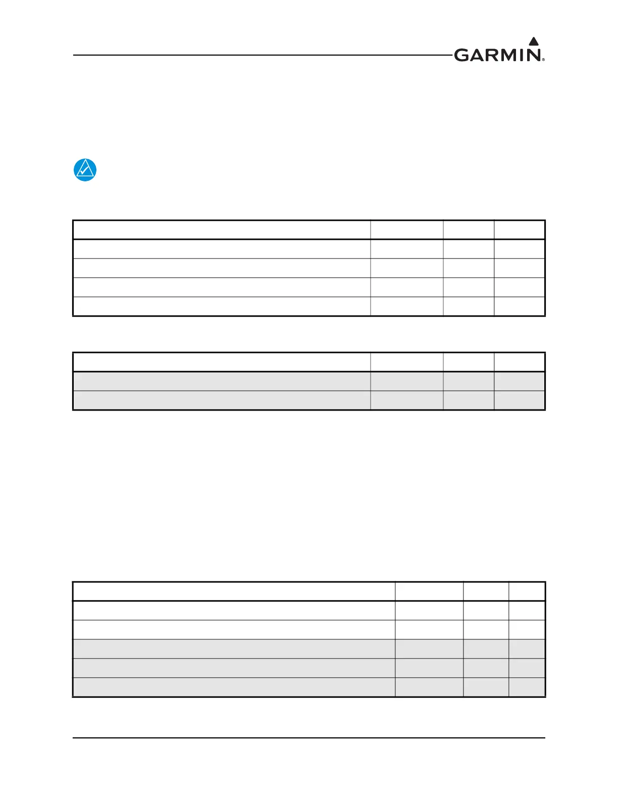
23.14.2 Aircraft Power
The GSU 25 can operate using power from one or both inputs (AIRCRAFT POWER 1 AND AIRCRAFT
POWER 2). The pins are internally connected using diodes to prevent current from flowing between the
two power inputs. AIRCRAFT POWER 2 is for connecting to an alternate power source, such as on
aircraft with two electrical buses.
NOTE
The GSU 25 magnetometer power output pin is intended for use only with the GMU 22.
Do not connect the GMU 11 or any other device to this pin.
The GSU 25 outputs supply voltage to the GMU 22 using pins 6 & 7.
23.14.3 Serial Data
23.14.3.1 RS-232
2 Channels of RS-232 RX, and 3 Channels of RS-232 TX data.
RS-232 1: Can optionally be connected to a GDU display to provide a redundant path for attitude data.
Also used to configure a GSU 25 as ADAHRS #3.
RS-232 2: Transmits data to the GMU 22.
RS-232 3: Connects to a GTX™ transponder to provide pressure altitude data and remote transponder
control. Primary transponder connection is made to ADAHRS 1. A second transponder connection to
ADAHRS 2 can be made for redundancy of this datapath.
Pin Name Connector Pin I/O
AIRCRAFT POWER 1 J251 7 In
AIRCRAFT POWER 2 J251 8 In
POWER GROUND J251 6 --
POWER GROUND J251 9 --
Pin Name Connector Pin I/O
+12V MAGNETOMETER POWER J252 6 Out
MAGNETOMETER GROUND J252 7 --
Pin Name Connector Pin I/O
RS-232 RX 1 J251 4 In
RS-232 TX 1 J251 5 Out
RS-232 TX 2 J252 15 Out
RS-232 RX 3 J252 10 In
RS-232 TX 3 J252 9 Out

 Loading...


