190-01115-01 G3X™/G3X Touch™ Avionics Installation Manual
Rev. AV Page E-11
E.5 Unit Installation
Fabrication of a wiring harness is required. Sound mechanical and electrical methods and practices are
recommended for installation of the GDU 37X. Refer to Section 2.3
for wiring considerations, and to
Section 23.3
for pinouts.
Connector kits include backshell assemblies. Garmin’s backshell connectors give the installer the ability to
quickly and easily terminate shield grounds at the backshell housing. The instructions needed to assemble
the backshell connector w/Shield Block grounding system are located in Section 22
.
NOTE
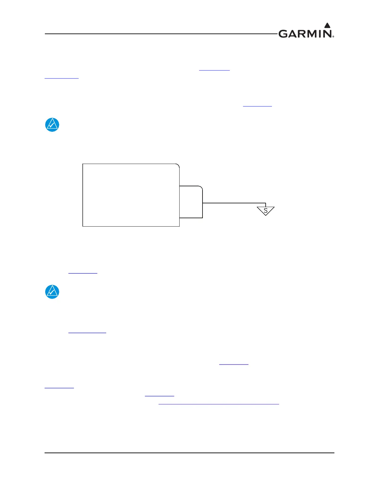
The GDU 37X rear connector (J3701) is electrically isolated. For installations using
shielded cables, a ground pin must be tied to the connector shell (Figure E-5).
Figure E-5 Grounded Connector Shell
E.6 Antennas
Refer to Section 20 for antenna information.
NOTE
GDU 37X units cannot be used with GA 35, GA 36, or GA 37 antennas.
E.7 Mounting Requirements
Refer to Appendix E.8 for outline and installation drawings.
E.7.1 Unit Installation
The GDU 37X is installed by holding the unit flush with the instrument panel and fastening the four
captured 3/32” hex socket head screws to the panel as shown in Figure E-8
.
E.7.2 Panel Cutout Template
Figure E-6
can be used as a template when marking the panel for cutout. Dimensions on the figure are to
verify accuracy of printout only, see Figure E-8
for complete cutout dimensions. A .dxf version of the
drawing is also available for download at https://support.garmin.com/support/manuals
.
GDU 37X
SIGNAL GROUND 35
P3701
GARMIN SHIELD
BLOCK GROUND

 Loading...


