190-01115-01 G3X™/G3X Touch™ Avionics Installation Manual
Rev. AV Page 30-218
30.4.32.27 Advanced Gauge Configuration
The ability to support dynamic gauge range markings and alerts is supported through the use of engine/
airframe logic signals, which are used to allow one engine/airframe parameter to affect the behavior of
another, or even to affect itself. A logic signal is a simple binary value, which can be in one of two states:
"set" (1) or "clear" (0), based on the real-time sensor input value of the associated gauge. Up to 10 logic
signals are supported, numbered 1 through 10. When editing a gauge range marking or discrete input, the
Mode setting is used to configure how it interacts with logic signals (see Figure 30-66).
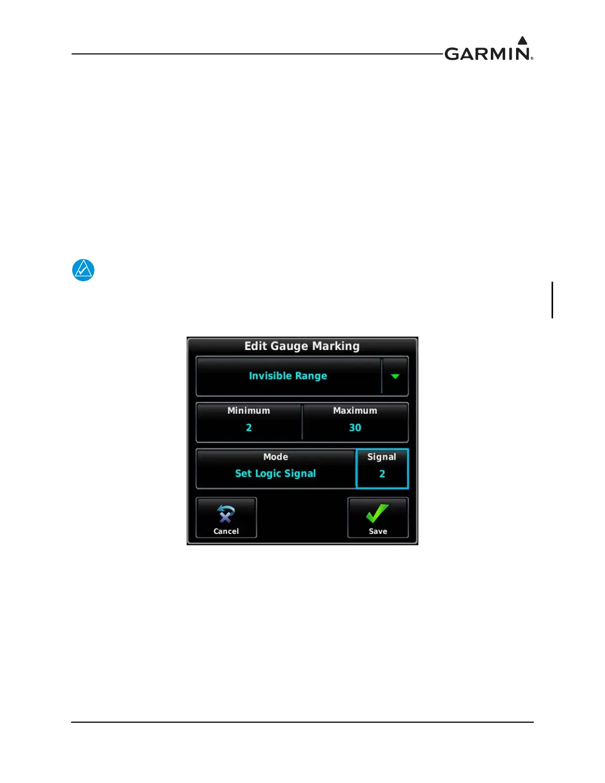
An individual gauge range marking can be configured to set a particular logic signal, which will cause that
logic signal to be set any time the gauge value is within that range. This includes support for "Invisible"
gauge range markings that do not appear on the screen and exist only to set a logic signal. If multiple gauge
range markings are configured to set the same logic signal, the state of that logic signal will involve a
logical OR operation.
NOTE
If a logic signal is not associated with a gauge marking parameter, it will automatically
default to the “set” state (if the configured requirements for speed, altitude, and time delay
are met).
Figure 30-66 Edit Gauge Marking - Logic Signal Set By Invisible Range

 Loading...


