190-01115-01 G3X™/G3X Touch™ Avionics Installation Manual
Rev. AV Page 23-7
23.1.8 Lighting Bus
The GAD 27 can monitor from 1 to 3 lighting bus control inputs, supply up to 3 DC lighting outputs, and
up to 3 PWM lighting outputs. The +12V OUTPUT pin can be used to provide supply voltage for
potentiometer inputs used to vary the lighting bus outputs. The DC Lighting outputs provide a reference
voltage only, 10mA max, and do not power lights. Attempting to source more than 10 mA of current from
these DC reference outputs may damage them.
The DC Lighting outputs are a variable DC voltage (output voltage is based on the lighting control input
voltage) that is used to vary the brightness of the lighting.
The PWM lighting outputs (pins 45, 46, 47) are active low, and can sink a maximum of 500 mA average
current. The pulse width modulation (PWM) of the output signal (square wave) is varied to control the
brightness of the lighting.
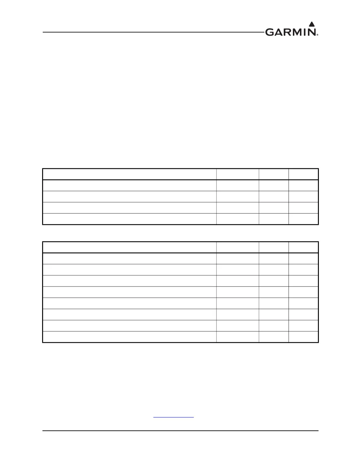
Lighting Bus Inputs
Lighting Bus Outputs
23.1.9 External Lighting Discrete Inputs
The GAD 27 has 3 active-low discrete lighting inputs. The Light 1 and Light 2 inputs can be connected to
cockpit switches to control the operation of the two supported aircraft external lights. Typically these
inputs are used to control one or two landing lights, or a pair of separate landing and taxi lights.
The Alternating Flash On input can optionally be used to support a cockpit switch to control the flashing
behavior of the aircraft's external lights. If this input is not connected, the external lights may still be set to
flash automatically based on airspeed (see Section 30.4.33
).
Pin Name Connector Pin I/O
LIGHTING BUS GROUND J271 38 --
LIGHTING CONTROL IN 1 J271 39 In
LIGHTING CONTROL IN 2 J271 40 In
LIGHTING CONTROL IN 3 J271 41 In
Pin Name Connector Pin I/O
+12V OUTPUT J271 37 Out
LIGHTING BUS GROUND J271 38 --
DC LIGHTING 1 J271 42 Out
DC LIGHTING 2 J271 43 Out
DC LIGHTING 3 J271 44 Out
PWM LIGHTING 1 J271 45 Out
PWM LIGHTING 2 J271 46 Out
PWM LIGHTING 3 J271 47 Out

 Loading...


