190-01115-01 G3X™/G3X Touch™ Avionics Installation Manual
Rev. AV Page 22-16
22.4 Thermocouple Installation into a Backshell
Table 22-5 lists parts needed to install a Thermocouple, the item numbers correspond to Figure 22-10 and
Figure 22-11
. Parts for this installation are included in the Thermocouple Kit (011-00981-00), which is
included in the G3X w/GSU 73 Installation Kit (K10-00017-00).
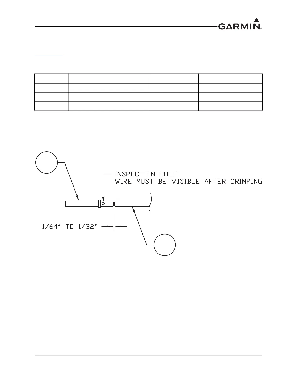
1. Strip back approximately 0.17 inches of insulation from both the positive and negative
thermocouple leads (item 1, Figure 22-10) and crimp a pin (item 2, Figure 22-10) to each lead. It is
the responsibility of the installer to find the proper length of insulation to be removed. Wire must
be visible in the inspection hole after crimping and the insulation must be 1/64 – 1/32 inches from
the end of the contact as shown in Figure 22-10.
Figure 22-10 Insulation/Contact Clearance
Table 22-5 Thermocouple Kit GPN 011-00981-00
Item # Description Qty. Needed PN or MIL spec
1 3” Thermocouple, K type 1 925-L0000-00
2 Pins #22 AWG 2 336-00021-00
3 Screw 1 211-60234-08

 Loading...


