190-01115-01 G3X™/G3X Touch™ Avionics Installation Manual
Rev. AV Page 15-2
15.1.1 Status LED
The GPS 20A has two LEDs on its outer case that indicate its current unit and GPS status (Figure 15-1
).
The unit status LED is in the middle of the outer case between the coax and 9 pin connectors. See Section
31.1.1 for details.
The GPS status LED is on the edge of the outer case, to the left of the coax connector. Table 15-1 lists the
GPS status indications.
15.2 Statement of Compliance (per AC 90-114A CHG1)
The Garmin GPS 20A, while not TSO approved, meets the ADS-B Out position source performance
requirements for FAR 91.227 compliance when used in combination with a Mode S ADS-B Out
transponder meeting the requirements of TSO-C166b and installed in accordance with the instructions in
this document. Example transponders which may be used in combination with the GPS 20A for FAR
91.227 compliance are the Garmin GTX™ 330ES transponder, GTX 23ES, GTX 35R, GTX 45R,
GTX 345/345R, and GTX 335/335R.
15.3 Equipment Available
15.3.1 Required Equipment
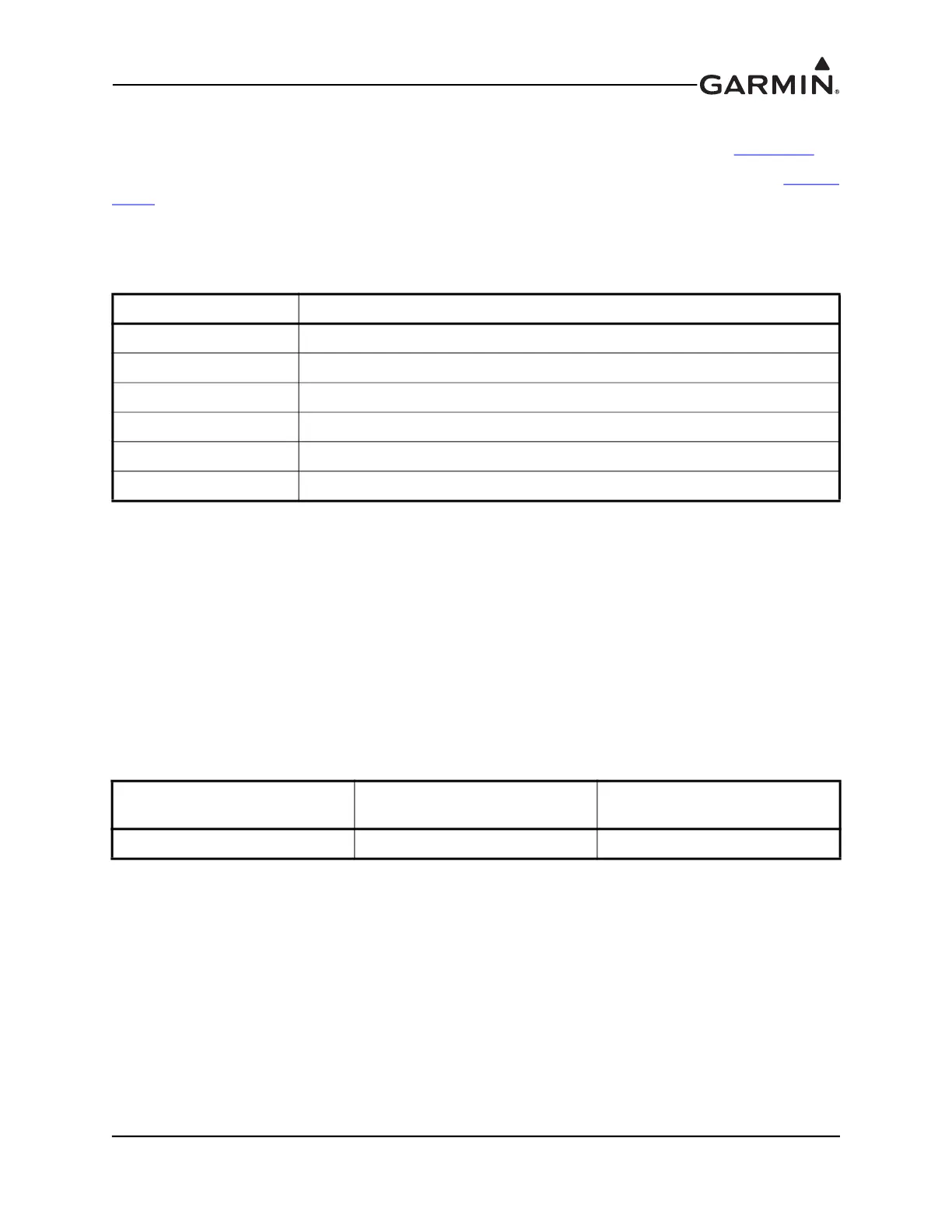
Table 15-1 GPS Status LED Indications
LED Indication Description
Red GPS hardware failure
No Light GPS acquiring, low signal to noise ratio or antenna not connected
Slow Flashing Green GPS acquiring, good signal to noise ratio
Fast Flashing Green GPS fix acquired
Steady Green GPS WAAS fix acquired
Alternating Red/Green CAN bus network error, two similar devices are configured with same unit ID
Table 15-2 GPS 20A Part Numbers
Model
Assembly Part
Number
Unit Only Part
Number
GPS 20A 010-01546-00 011-03913-00

 Loading...


