190-01115-01 G3X™/G3X Touch™ Avionics Installation Manual
Rev. AV Page 23-12
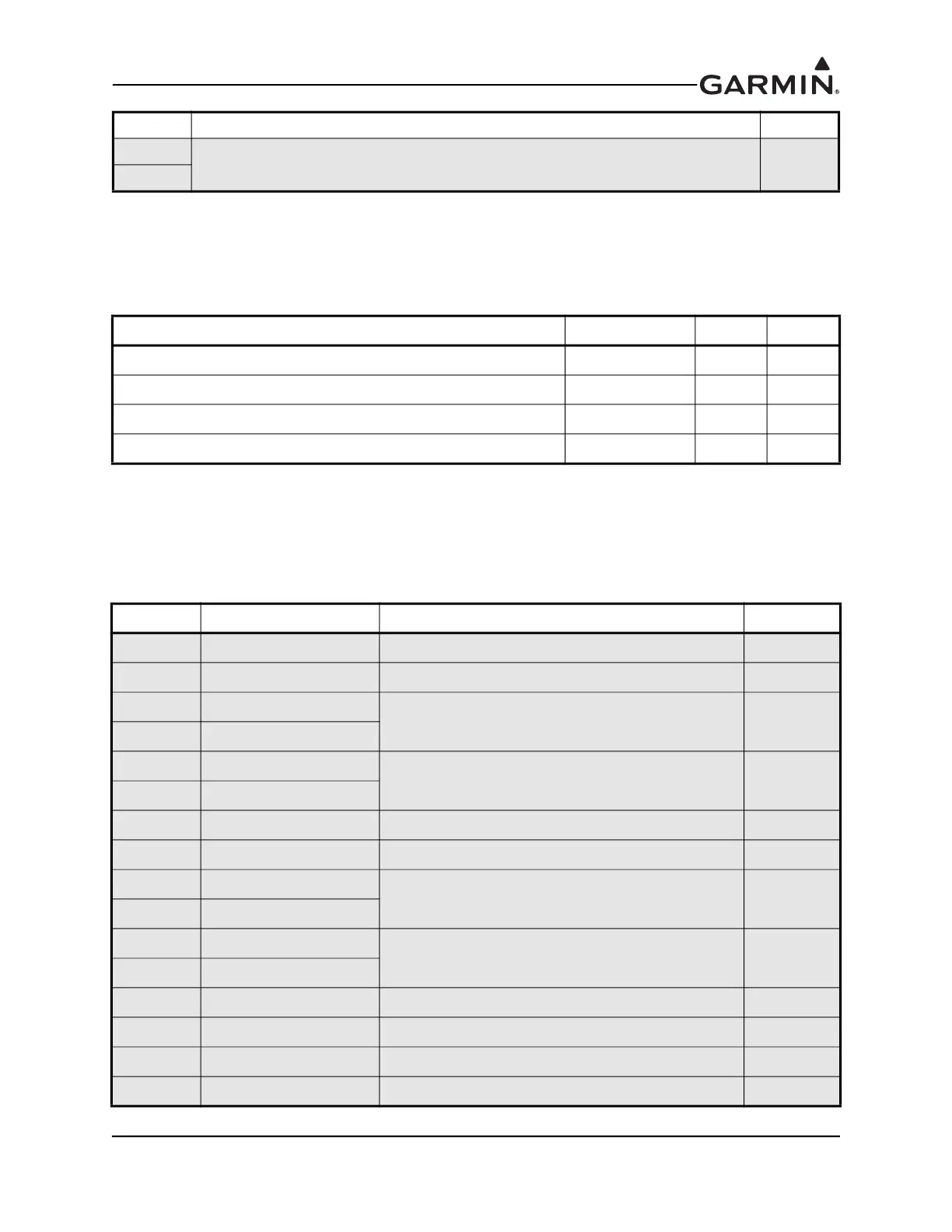
23.2.3 Power
This section covers the power input requirements. AIRCRAFT POWER 1 and AIRCRAFT POWER 2 are
“diode ORed” to provide power redundancy.
23.2.4 ARINC 429 RX/TX
The ARINC 429 outputs conform to ARINC 429 electrical specifications when loaded with up to 5
standard ARINC 429 receivers. Each ARINC 429 Transmitter pin is physically connected to two DSUB
pins. When running one transmitter to two receivers use two separate pins to avoid splicing wires.
Running one transmitter to more than two receivers will require splicing wires.
24
ARINC TX 1A Out
25
Pin Name Connector Pin I/O
AIRCRAFT POWER 1 J291 7 In
AIRCRAFT POWER 2 J291 8 In
POWER GROUND J291 6 --
POWER GROUND J291 9 --
Pin Connector Pin Name I/O
23 J292 ARINC RX 1A In
11 J292 ARINC RX 1B In
24 J292
ARINC TX 1A Out
25 J292
12 J292
ARINC TX 1B Out
13 J292
22 J292 ARINC RX 2A In
10 J292 ARINC RX 2B In
18 J292
ARINC TX 2A Out
19 J292
6 J292
ARINC TX 2B Out
7 J292
17 J292 ARINC RX 3A In
5 J292 ARINC RX 3B In
16 J292 ARINC RX 4A In
4 J292 ARINC RX 4B In
Pin Pin Name I/O
*GAD 29B/29D only
 Loading...


