190-01115-01 G3X™/G3X Touch™ Avionics Installation Manual
Rev. AV Page 21-16
21.2.8 Twin-Engine Applications
A GDU 4XX system using two GEA 24 units can monitor data from two engines with up to 6 cylinders
each. Engine #1 is connected to GEA 24 #1, and engine #2 is connected to GEA 24 #2. Data from both
engines is presented on the same GDU display. Due to its larger display size, the GDU 46X is preferred
over the GDU 45X or GDU 47X for twin-engine applications.
The two GEA 24s in a twin-engine installation use the same input configuration for analog and digital
inputs, with a configuration choice to allow data for a particular input to be monitored from both GEA 24s,
or from #1 only. The second GEA 24 may also be used to support additional discrete inputs. For
information on configuring twin-engine sensor inputs, see Section 30.4.6
and Section 30.4.32.3.
21.2.9 Rotorcraft Applications
Rotorcraft engine monitoring can be accomplished with a GDU 4XX system, using the engine sensor
application information in Section 21.2.1
through Section 21.2.7. Typically, the GEA 24 RPM 1 input is
used to monitor rotor RPM.
A GDU 4XX system using two GEA 24 units can be used to monitor engine information for a twin-engine
rotorcraft, as described in Section 21.2.8
.
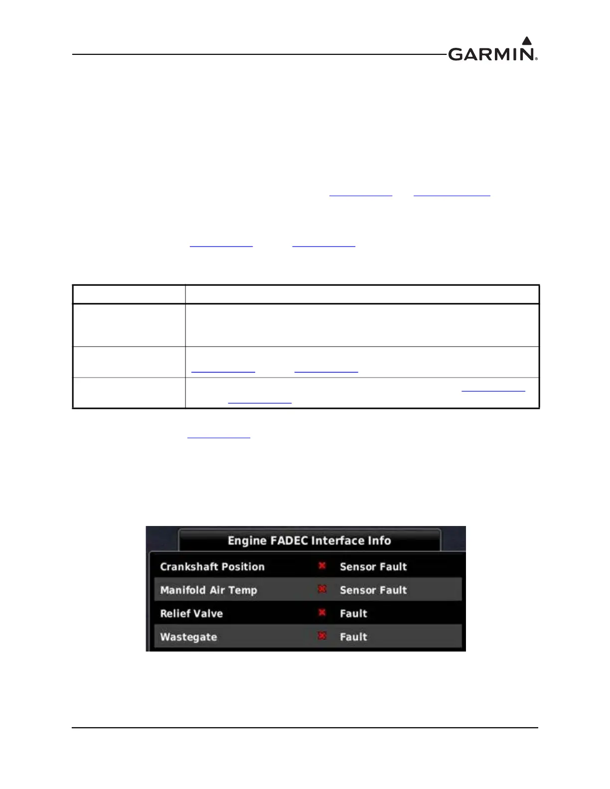
21.2.10 FADEC Engine Status
When used with a digital interface to a FADEC engine, FADEC status and maintenance information can
be viewed in configuration mode or in normal mode from the Engine page Option Menu. To view FADEC
status, access the configuration mode System Information page and highlight the FADEC item. The
specific FADEC status data that is displayed (Figure 21-2) will vary based on the configured engine type.
Figure 21-2 Configuration Mode FADEC Interface Status
In normal mode, caution and warning indications from the FADEC interface are displayed in the form of
CAS messages. Refer to the G3X Touch™ Avionics Pilot’s Guide (190-01754-00) for further information.
Table 21-12 Sensors for Rotorcraft Applications
Sensor Type Details
Rotor RPM
Select "Custom" configuration for GEA 24 RPM1 input and enter frequency-
to-RPM calibration. A Sandia ST26 tachometer signal converter may be
required to provide proper digital signal conditioning.
Engine RPM
Select appropriate configuration for GEA 24 RPM 2 input as described in
Section 21.2.1 through Section 21.2.7.
Other engine sensors
Select appropriate sensors and configuration as described in Section 21.2.1
through Section 21.2.7.

 Loading...


