190-01115-01 G3X™/G3X Touch™ Avionics Installation Manual
Rev. AV Page F-11
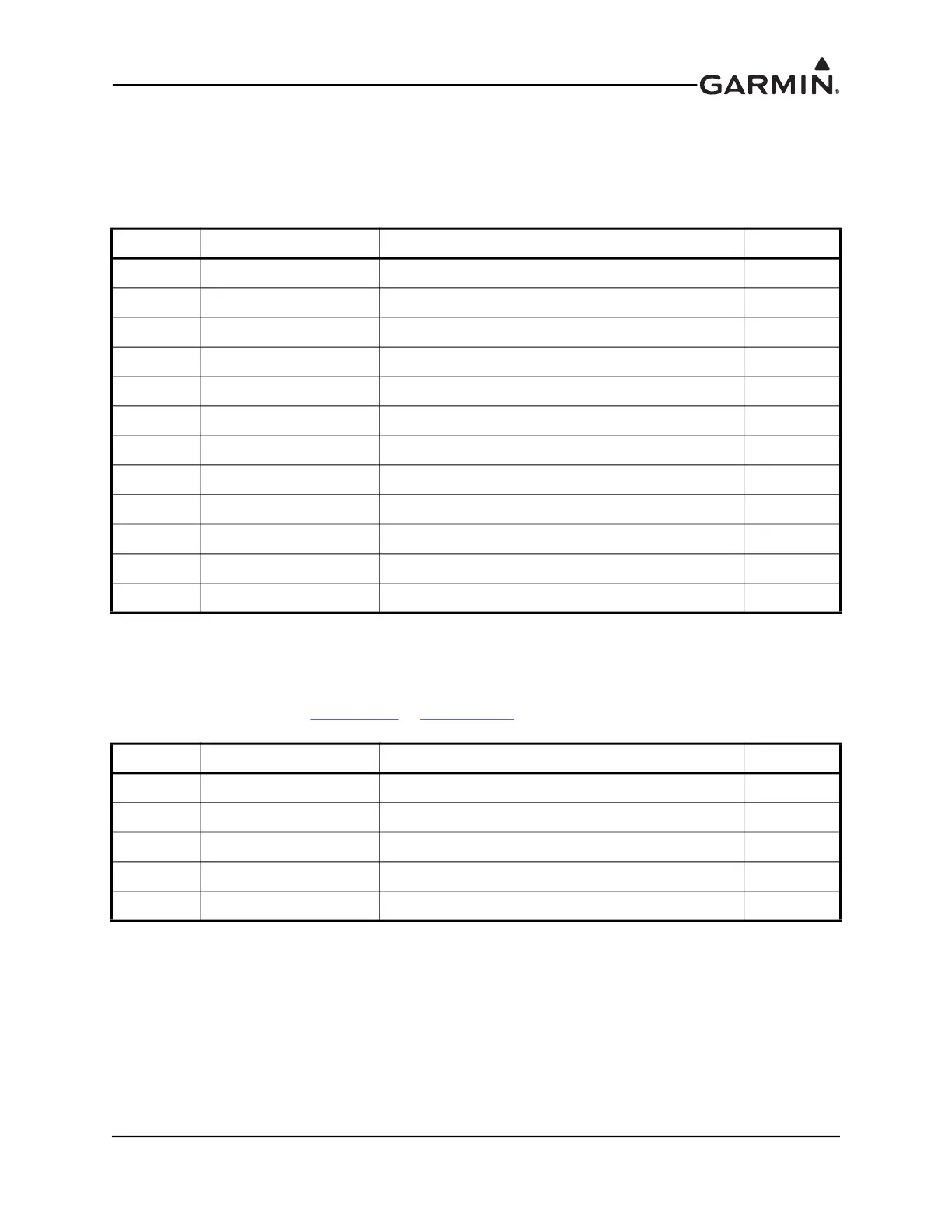
F.5.4 Serial Data Electrical Characteristics
F.5.4.1 ARINC 429 Input/Output
The ARINC 429 outputs conform to ARINC 429 electrical specifications when loaded with up to 5
standard ARINC 429 receivers.
F.5.4.2 RS-232 Input/Output
The RS-232 outputs conform to EIA Standard RS-232C with an output voltage swing of at least ±5 V
when driving a standard RS-232 load. RS-232 OUT 2 is not currently active. RS-232 IN/OUT 3 is used for
connection to a transponder (Figure G-2.2
& Figure G-2.3), and is not configurable (always on by default).
Pin Connector Pin Name I/O
20 J731 ARINC 429 OUT 1A OUT
21 J731 ARINC 429 OUT 1B OUT
22 J731 ARINC 429 OUT 2A OUT
23 J731 ARINC 429 OUT 2B OUT
25 J731 ARINC 429 IN 1A IN
26 J731 ARINC 429 IN 1B IN
27 J731 ARINC 429 IN 2A IN
28 J731 ARINC 429 IN 2B IN
30 J731 ARINC 429 IN 3A IN
31 J731 ARINC 429 IN 3B IN
32 J731 ARINC 429 IN 4A IN
33 J731 ARINC 429 IN 4B IN
Pin Connector Pin Name I/O
15 J731 MAGNETOMETER RS-232 OUT OUT
16 J731 RS-232 IN 2 (RESERVED) IN
17 J731 RS-232 OUT 2 (RESERVED) OUT
18 J731 RS-232 IN 3 (TRANSPONDER) IN
19 J731 RS-232 OUT 3 (TRANSPONDER) OUT

 Loading...


