190-01115-01 G3X™/G3X Touch™ Avionics Installation Manual
Rev. AV Page 22-18
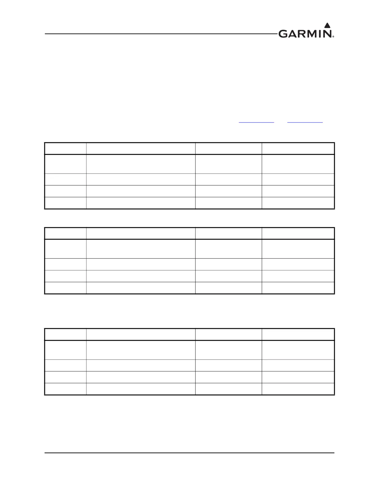
22.5 Configuration Module Installation into a Backshell
Table 22-6 & Table 22-7 list parts needed to install a Jackscrew Configuration Module with pins or with
sockets. Parts for these installations are included in the 011-00979-20 and 011-00979-22 kits, which are
included in the G3X w/GSU 73 Installation Kit (K10-00017-00).
Configuration modules are to be installed in the backshells of the P732 connector for the GSU 73 (use
011-00979-20 in Table 22-6), the P3701 connector for GDU™ 37X display designated as PFD1
(use 011-00979-22 in Table 22-7), or the P4X02 connector for the GDU 4XX designated as PFD1 (use
010-12253-00 in Table 22-8)
Item numbers in Table 22-6, Table 22-7, and Table 22-8 correspond to Figure 22-12
and Figure 22-13.
Table 22-6 GPN: 011-00979-20 – Kit (w/EEPROM and pins)
Item # Description Qty. Needed GPN or MIL spec
1
Potted Module (w/EEPROM and
Temp.sensor)
1 011-02179-00
3 4 cond. Cable harness 1 325-00122-00
4 Pins Size 22D 4 336-00021-00
10 Pan head screw 1 211-60232-07
Table 22-7 GPN: 011-00979-22 – Kit (w/EEPROM and sockets)
Item # Description Qty. Needed GPN or MIL spec
1
Potted Module (w/EEPROM and
Temp.sensor)
1 011-02179-00
3 4 cond. Cable harness 1 325-00122-00
9 Socket, Size 20, 26-30 AWG 4 336-00022-01
10 Pan head screw 1 211-60232-07
Table 22-8 GPN: 010-12253-00 – Config Module (w/EEPROM, Temp, & Connext® computer
application)
Item # Description Qty. Needed GPN or MIL spec
1
Config Module (w/Sockets,
Jackscrew, Temp, Connext)
1 011-03702-00
3 4 cond. Cable harness 1 325-00122-00
9 Socket, Size 20, 26-30 AWG 5 336-00022-01
10 Pan head screw 1 211-60232-07

 Loading...


