190-01115-01 G3X™/G3X Touch™ Avionics Installation Manual
Rev. AV Page 5-8
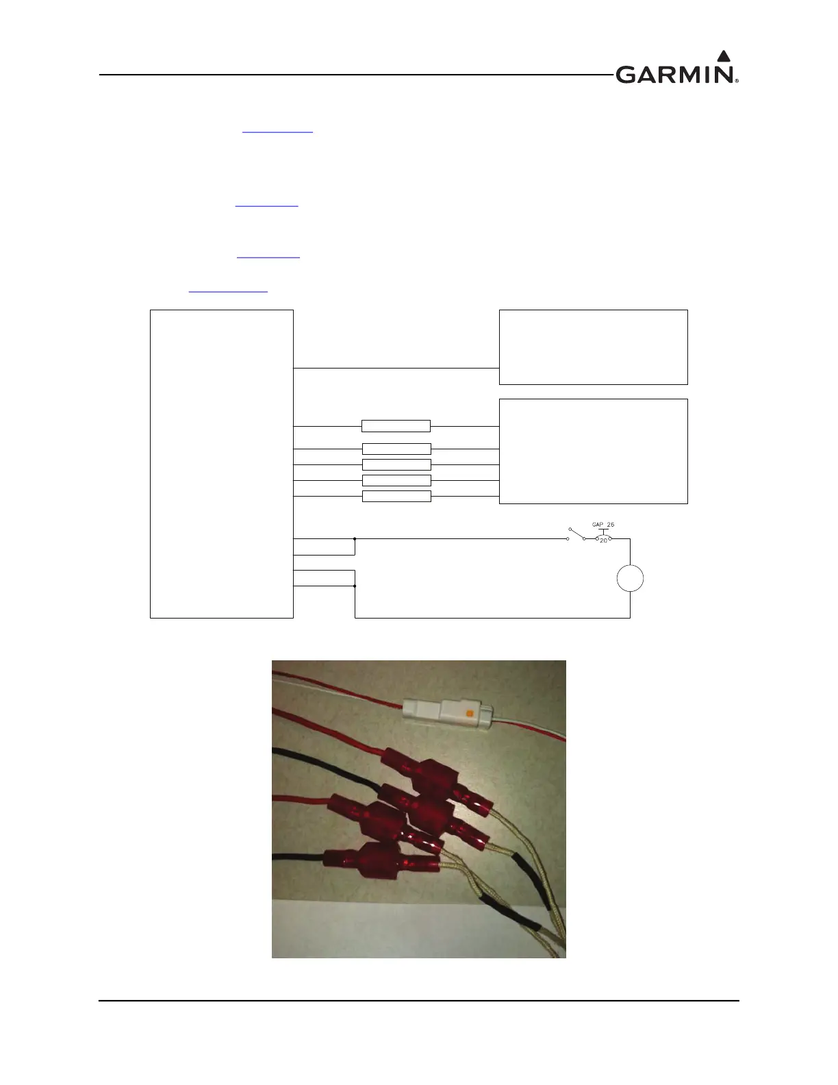
5.5.3 Control Box Installation (-20 version only)
Mount the control box (Figure 5-11
) to a suitable mounting location within two feet of the GAP 26 using
(4) #4 or #6 pan or hex head screws (choose screw length that is appropriate to mounting location).
Connect the white connector from the probe to the white connector from the control box (this allows the
control box to sense probe temperature). Connect the red connectors from the probe to the red connectors
from the control box, (Figure 5-9
) this provides power and ground to the heaters. The red wires with red
connectors from the control box connect to the plain wires with red connectors from the heater and the
black wires with red connectors from the control box connect to the banded wires with red connectors from
the heater (Figure 5-8, Figure 5-9
). The bare red and black heater wires from the control box should be
connected to 14 VDC as shown in Figure 5-8. The bare blue wire from the control box can be run to a spare
discrete input (Section 5.5.4
).
Figure 5-8 011-02964-20 Probe Wiring
Figure 5-9 011-02964-20 Probe to Control Box Connectors
-20 VERSION GAP 26
HEATER CONTROL BOX
BLACK WIRE (BARE)
BLACK WIRE (BARE)
RED WIRE (BARE)
RED WIRE (BARE)
-20 VERSION GAP 26 PROBE
BLACK WIRE (CONN.)
BLACK WIRE (CONN.)
RED WIRE (CONN.)
RED WIRE (CONN.)
BANDED WIRE (CONN.)
BANDED WIRE (CONN.)
PLAIN WIRE (CONN.)
PLAIN WIRE (CONN.)
WIRE W/WHITE CONN.
WIRE W/WHITE CONN.
GEA 24, GSU 73, OR GAD 27
GEA 24, GSU 73, OR GAD 27
(OPTIONAL)
DISCRETE INPUT
BLUE WIRE
WHITE CONN.
RED CONN.
RED CONN.
RED CONN.
RED CONN.
20A
14V

 Loading...


