190-01115-01 G3X™/G3X Touch™ Avionics Installation Manual
Rev. AV Page 2-20
2.3.1.1 Backshell Assemblies
Connector kits include backshell assemblies. The backshell assembly houses the configuration module and
a thermocouple reference junction. Garmin’s backshell connectors give the installer the ability to quickly
and easily terminate shield grounds at the backshell housing. The instructions needed to install the
Jackscrew Backshell, Configuration Module, Shield Block Ground, and Thermocouple are located in
Section 22
.
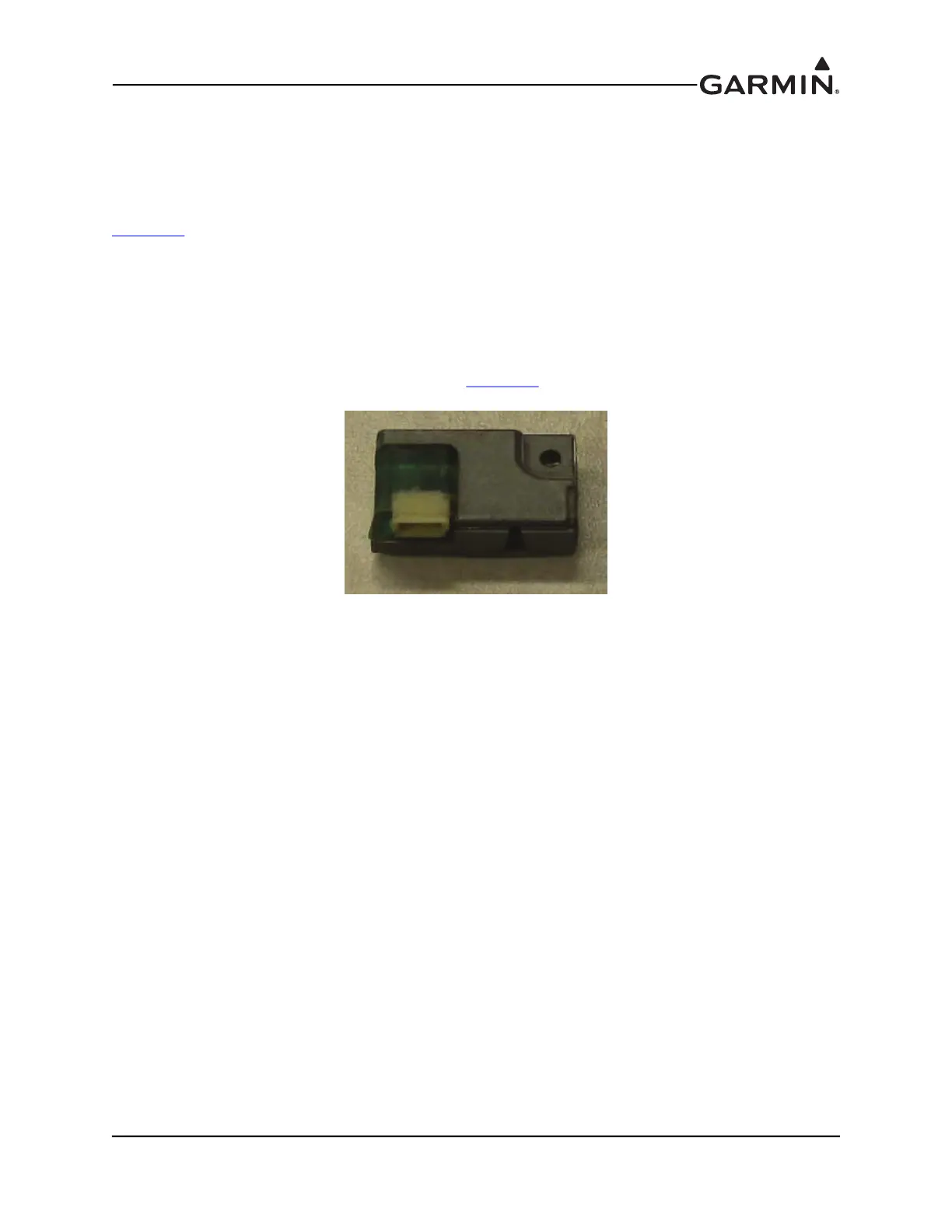
2.3.1.2 Configuration Module
The G3X system is designed to store configuration and calibration data in multiple locations to retain the
configuration of the system during maintenance. A configuration module (Figure 2-2 and Figure 2-3) is
installed in the connector backshell of the PFD1 display to store important configuration data. Only the
PFD1 display uses a configuration module; in systems using a GSU 73, an additional configuration module
is installed in the GSU 73 connector backshell. See Section 22
for installation instructions.
Figure 2-2 Original Green Configuration Module P/N 011-00979-20

 Loading...


