190-01115-01 G3X™/G3X Touch™ Avionics Installation Manual
Rev. AV Page 23-44
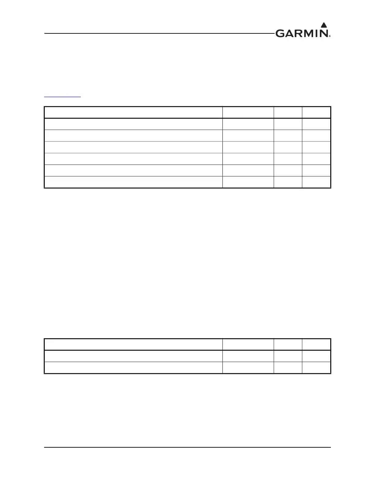
23.7.3 Serial Data
The RS-232 outputs conform to EIA Standard RS-232C with an output voltage swing of at least ±5 V
when driving a standard RS-232 load.
RS-232 channel 1 should be connected to an available RS-232 port on a GDU display. RS-232 channel 2
should be connected to the GSA 28 roll servo RS-232 port in a Garmin autopilot system (see
Figure 24-1.7
).
23.7.4 Lighting
The GMC 305 supports two internal backlighting buses, one for the mode (indicator) lights above the
buttons, and one for the button text, panel text, and knob backlighting.
Mode Indicator Backlighting - The lighting level for the mode (indicator) lights (triangles) above the
buttons is controlled by the photocell only, and is not affected by the lighting bus input (pins 11 & 12).
This makes sure the mode selection lights on the panel are always visible (and are independent of the
externally applied lighting bus).
Button Text, Panel Text, and Knob Backlighting - The GMC 305 can be installed to use either the built-in
photocell or the 14V lighting bus input for backlight control of the button text, panel text, and knob
backlighting. The photocell controls all backlighting when the lighting bus input is below 1.4VDC (or
unconnected). If the lighting bus input voltage is greater than 1.4VDC, the GMC 305 uses the lighting bus
input voltage (1.4VDC-14.0VDC range) as a reference voltage (not power source) to adjust the
backlighting for these items.
Most installations use the photocell backlighting (as it works well in most conditions) and leave pins 11
and 12 unconnected.
Pin Name Connector Pin I/O
RS-232 OUT 1 J3051 1 Out
RS-232 IN 1 J3051 2 In
RS-232 OUT 2 J3051 3 Out
RS-232 IN 2 J3051 4 In
SIGNAL GROUND J3051 6 --
SIGNAL GROUND J3051 8 --
Pin Name Connector Pin I/O
LIGHTING BUS HI J3051 11 In
LIGHTING BUS LO* J3051 12 In
*Connect to power ground if pin 11 is used

 Loading...


