190-01115-01 G3X™/G3X Touch™ Avionics Installation Manual
Rev. AV Page 23-21
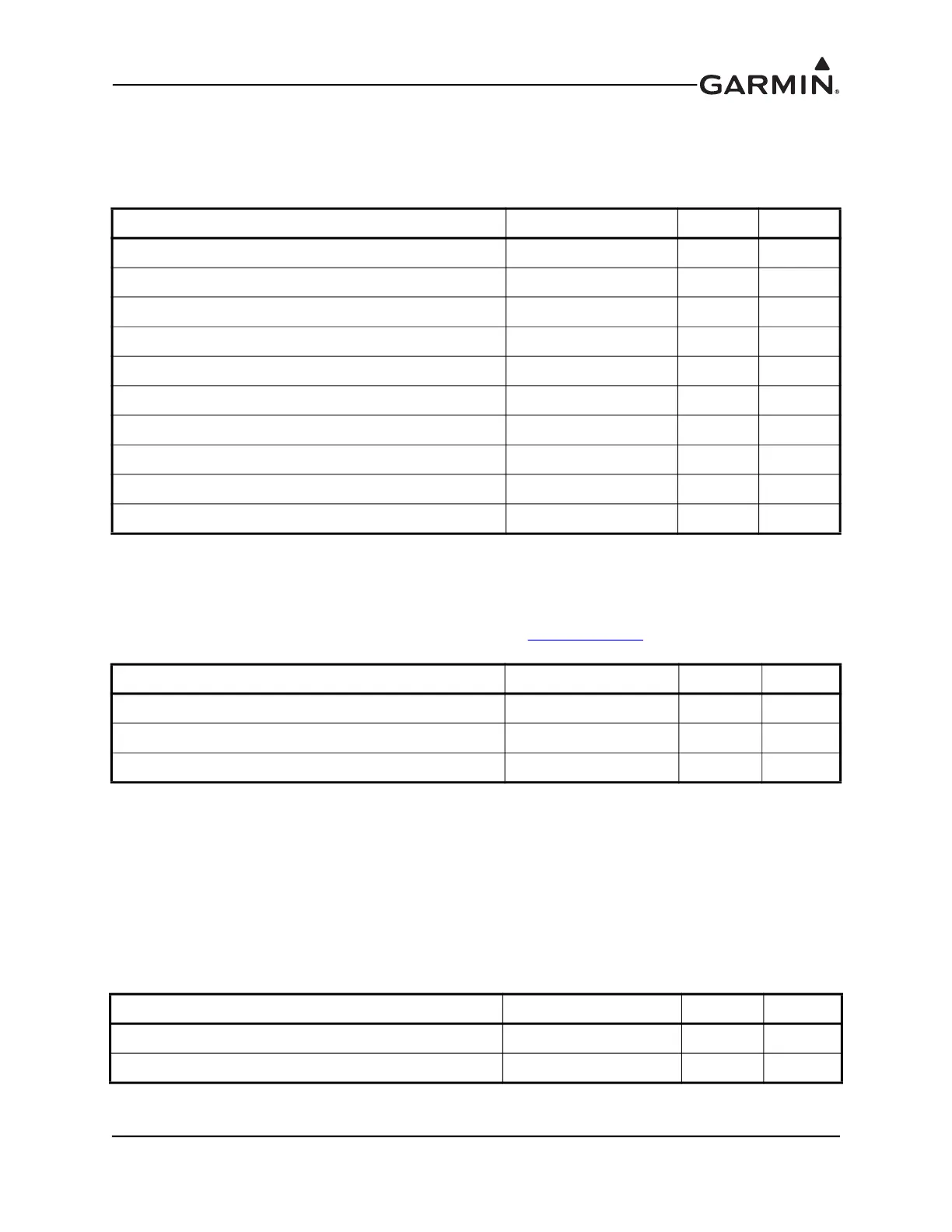
23.3.8 Serial Data
23.3.8.1 RS-232
5 Channels of RS-232 I/O data.
23.3.8.2 CAN Bus
This data bus conforms to the BOSCH standard for Controller Area Network 2.0-B. This bus complies
with ISO 11898. CAN BUS TERMINATION should be connected to CAN BUS LO for the GDU that is
located at the end of the bus (farthest from the GSU 73), see Section 2.3.1.3.3
for details.
23.3.9 Lighting
The GDU 4XX display and keys can be configured to track 28 VDC or 14 VDC lighting busses using these
inputs. These inputs are reference voltage inputs (not power inputs) with a high impedance of
~100 kΩ for pin 43 and ~200 kΩ for pin 26. This backlight level reference signal may be supplied with
something as simple as a 10K potentiometer connected to power and ground (drawing 1 mA @ 14 VDC).
The center tap on this potentiometer is connected to one of the pins (43 or 26) in the following table. For
providing this reference signal to more than one device, a commercially available regulated backlight
voltage reference is recommended.
Pin Name Connector Pin I/O
RS-232 IN 1 P4X02 47 In
RS-232 OUT 1 P4X02 48 Out
RS-232 IN 2 P4X02 14 In
RS-232 OUT 2 P4X02 30 Out
RS-232 IN 3 P4X02 29 In
RS-232 OUT 3 P4X02 13 Out
RS-232 IN 4 P4X02 23 In
RS-232 OUT 4 P4X02 40 Out
RS-232 IN 5 P4X02 24 In
RS-232 OUT 5 PX02 41 Out
Pin Name Connector Pin I/O
CAN BUS HI PX02 46 I/O
CAN BUS LO P4X02 45 I/O
CAN BUS TERMINATION P4X02 28 --
Pin Name Connector Pin I/O
14V LIGHTING BUS HI P4X02 43 In
28V LIGHTING BUS HI P4X02 26 In

 Loading...


