190-01115-01 G3X™/G3X Touch™ Avionics Installation Manual
Rev. AV Page F-14
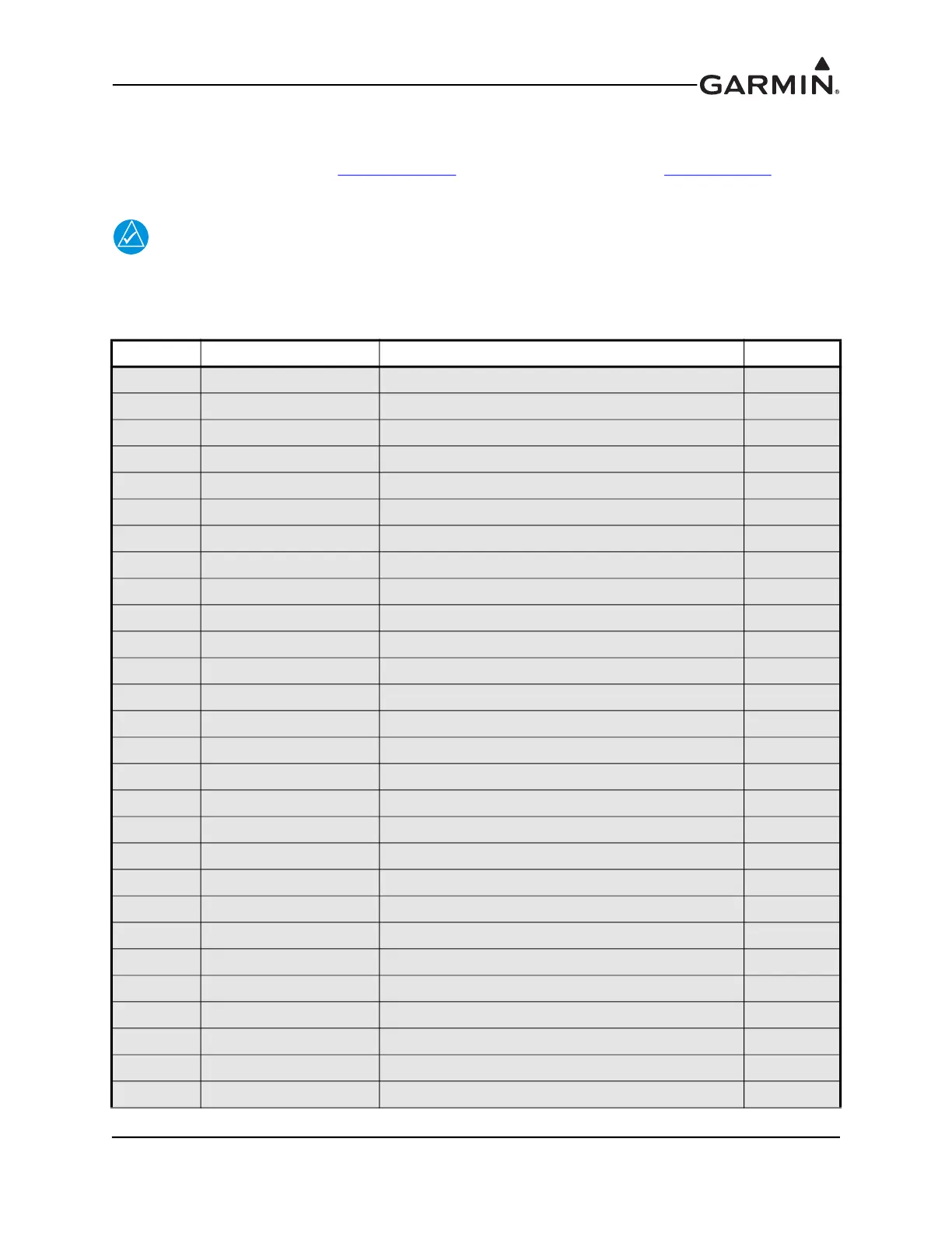
F.5.6 Analog Input Configuration
Some analog inputs are multi-purpose capable and have several configuration options. These inputs are
configured by the GDU (refer to Appendix H.4.19
for GDU 37X systems and to Section 30.4.32 for
GDU 4XX systems) and are capable of reading any voltage up to 40 Vdc.
NOTE
If installing an ungrounded thermocouple to an Analog In input, a DC reference must be
added to the LO input. This can be accomplished by adding a resistance of 1 MΩ or less
between ground and the Analog In LO input the ungrounded thermocouple is installed on.
Pin Connector Pin Name I/O
61 J732 CHT 1 HI IN
41 J732 CHT 1 LO IN
21 J732 CHT 2 HI IN
1 J732 CHT 2 LO IN
2 J732 CHT 3 HI IN
22 J732 CHT 3 LO IN
60 J732 CHT 4 HI IN
40 J732 CHT 4 LO IN
73 J732 CHT 5 HI IN
53 J732 CHT 5 LO IN
33 J732 CHT 6 HI IN
13 J732 CHT 6 LO IN
63 J732 EGT 1 HI IN
43 J732 EGT 1 LO IN
23 J732 EGT 2 HI IN
3 J732 EGT 2 LO IN
24 J732 EGT 3 HI IN
4 J732 EGT 3 LO IN
62 J732 EGT 4 HI IN
42 J732 EGT 4 LO IN
30 J732 EGT 5 HI IN
29 J732 EGT 5 LO IN
34 J732 OIL TEMP HI IN
14 J732 OIL TEMP LO IN
72 J732 POS 5 / MISC TEMP HI IN
52 J732 POS 5 / MISC TEMP LO IN
25 J732 FUEL 1 HI IN
5 J732 FUEL 1 LO IN

 Loading...


