190-01115-01 G3X™/G3X Touch™ Avionics Installation Manual
Rev. AV Page F-18
F.5.12 Mounting Requirements
Mount the GSU 73 with the connectors aligned within 1.0 deg of either the longitudinal or lateral axis of
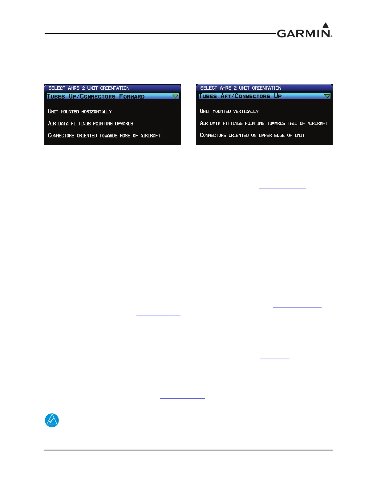
the aircraft. The direction of the unit will be accounted for during the calibration procedure as shown in
Figure F-6.
Figure F-6 AHRS Orientation Selection
The GSU 73 includes an extremely sensitive strap-down inertial measurement unit. It must be mounted
rigidly to the aircraft primary structure, preferably to a metallic structure to conduct heat away from the
unit. Do not mount the GSU 73 in an enclosed area, it should be mounted in a location that provides
adequate airflow to comply with the maximum outer case temperature listed in Appendix D.13.1
.
Do not use shock mounting to mount the GSU 73. Shock mounts used for other types of inertial systems
are not acceptable for the GSU 73 AHRS. The mounting system must have no resonance with the unit
installed. Excessive vibration may result in degraded accuracy.
The supporting plate must be rigidly connected to the aircraft primary structure through strong structural
members capable of supporting substantial loads. Avoid areas that are prone to severe vibration.
The GSU 73 should be mounted within 13 feet (4.0 meters) longitudinally and 6.5 feet (2.0 meters)
laterally of the aircraft center of gravity. In cases where the longitudinal distance from the CG is planned to
be greater than 6.5 feet (2.0 meters), it is preferable to mount the GSU 73 forward of the aircraft center of
gravity if possible, to enable better acceleration outputs for autopilot use. The mounting location for the
GSU 73 should be protected from rapid thermal transients, in particular, large heat loads from nearby high-
power equipment.
The GSU 73 must be leveled to within 3.0° of the in-flight level cruise altitude and an aircraft leveling and
offset calibration procedure carried out before flight. (This procedure is described in Appendix H.4.3.2
for
GDU™ 37X display systems and Section 30.4.7.2
for GDU 4XX systems.)
Avoid placing the GSU 73 within 1 inch of magnetically mounted antennas, speaker magnets, or other
strongly magnetic items.
F.5.13 Unit Mounting
For final installation and assembly, refer to the outline and installation drawing Figure F-7
of this manual.
1. Assemble the wiring harness and backshell connectors.
2. Assemble the pneumatic hoses and connectors.
3. Mount the unit to a suitable mounting location using (4 ea) #10-32 pan or hex head screws
(example) per the requirements in Appendix F.5.12
.
4. Connect backshell connector and hoses.
NOTE
When mounting the GSU 73 to the airframe, it is important to make sure that fastening
hardware is tight for proper unit operation.

 Loading...


