190-01115-01 G3X™/G3X Touch™ Avionics Installation Manual
Rev. AV Page 21-23
21.3.4 Pressure (Fuel, Manifold, Oil, and Coolant)
Select the pressure sensor from Table 21-1
that is best suited for the aircraft system and installation
location. Maximum system operating or surge pressures must not exceed the sensor's rated pressure.
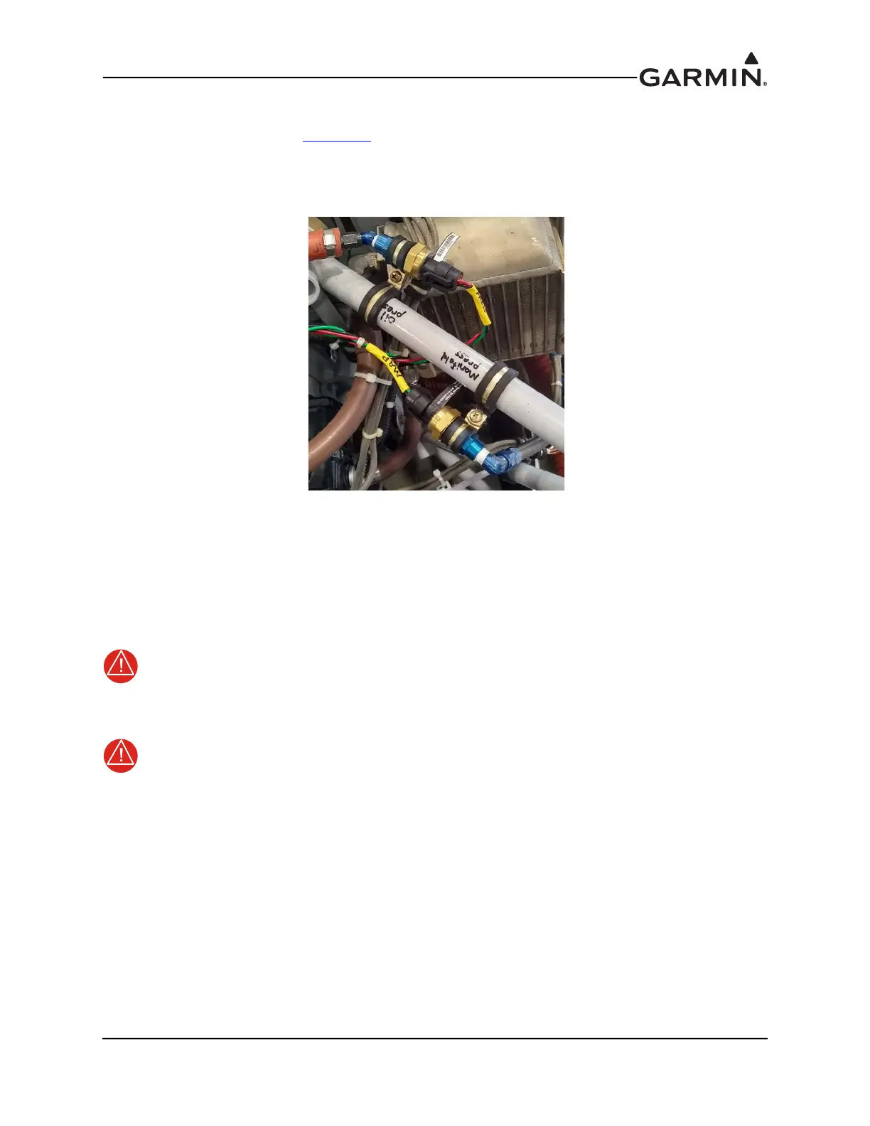
General Mounting Methods – The specified pressure transducers provide for two different mounting
options:
Figure 21-12 Pressure Transducer Mounting
a) Sensor body secured to the engine mount or firewall using an appropriately sized Adel
clamp (preferred)
OR
b) Mounted to a transducer mounting block located on the firewall. UMA sensor mounting
may require the use of a stainless steel AN911 fitting (union).
WARNING
The sensor must not be mounted directly to the engine. Mechanical failure of the sensor
could result in leaks and loss of pressure.
WARNING
Test all fuel, oil, and coolant pressure sensors for leakage following installation and before
flight.
Installation Guidance:
1. Hoses and fittings - Fuel and oil hoses installed in the engine compartment should meet TSO-C53a
Type C or D (fire resistant) and rated for the pressure, temperature, and be compatible with the fuel
or oil. Sensor hoses must be routed as far away from the aircraft exhaust system as practical and no
closer than 6 inches. Fittings should be AN/AS-spec or Mil-spec.
2. Sensors - Do not install sensors directly below fittings or components that may leak flammable
fluid. To prevent water from settling in the fuel pressure sensor and causing freeze damage, install
sensor with the electrical connector angling upward or with a hose/line with an upward bend that
will trap heavier water before entering the sensor.

 Loading...


