190-01115-01 G3X™/G3X Touch™ Avionics Installation Manual
Rev. AV Page 19-1
19 GTR 20 (VHF COMMUNICATIONS RADIO) INSTALLATION
This section contains general information as well as installation information for the GTR 20. Use this
section to mount the GTR 20 unit. Careful planning and consideration of the suggestions in this section are
required to achieve the desired performance and reliability from the GTR 20. The guidance of FAA
advisory circulars AC 43.13-1B and AC 43.13-2B, where applicable, may be found useful for making
retro-fit installations that comply with FAA regulations.
NOTE
A GTR 20 cannot be installed in a system that also includes a GDU™ 37X display. The
GTR 20 will only work with the G3X™ avionics system that uses the new GDU 4XX
displays. The GTR 20 is not supported with G3X installations using GDU 37X displays.
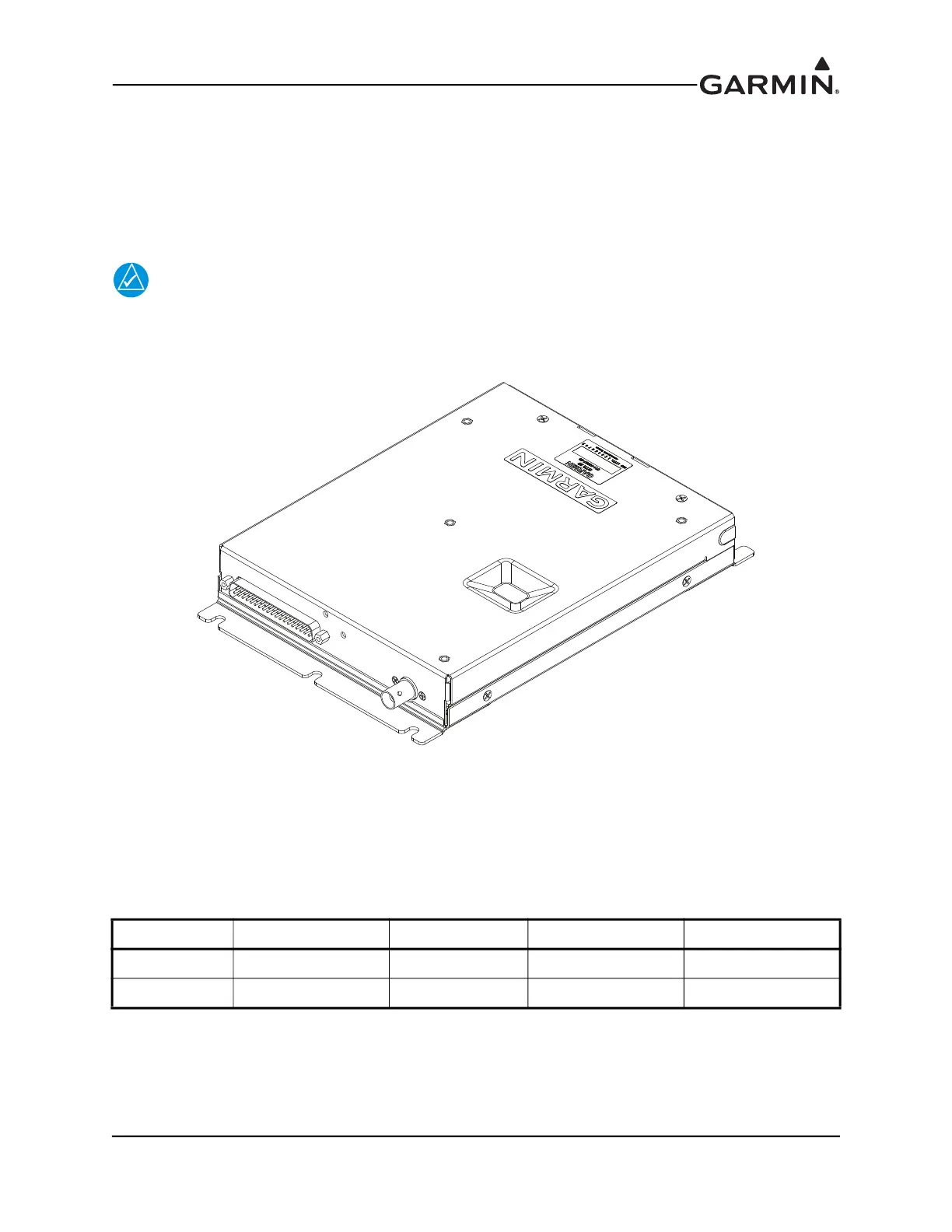
Figure 19-1 GTR 20 Unit View (shown with mounting brackets on ends)
19.1 Equipment Description
The GTR 20 is a transceiver that operates in the 118.000 to 136.975 MHz frequency range. The receiver
sensitivity SINAD is greater than 6dB when the RF level is -107 dBm with 30% modulation. The
transmitter power is 10 W carrier minimum.
Table 19-1 Available Units
Model Part Number TX Power (Watt) 8.33 KHz Spacing 25 KHz Spacing
GTR 20 011-03007-00 10 N/A Yes
GTR 20 011-03007-10 10 N/A Yes

 Loading...


