190-01115-01 G3X™/G3X Touch™ Avionics Installation Manual
Rev. AV Page E-9
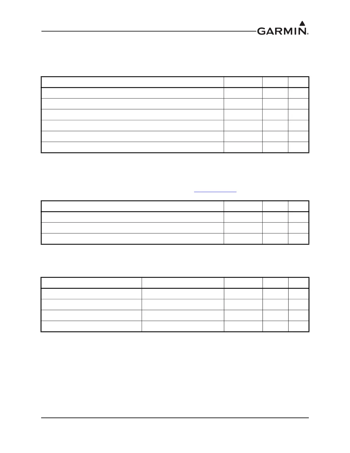
E.4.4 Serial Data
E.4.4.1 RS-232
3 Channels of RS-232 I/O data.
E.4.4.2 CAN Bus
This data bus conforms to the BOSCH standard for Controller Area Network 2.0-B. This bus complies
with ISO 11898. CAN BUS TERMINATION should be connected to CAN BUS LO for the GDU that is
located at the end of the bus (farthest from the GSU 73), see Section 2.3.1.3.3
for details.
E.4.4.3 Configuration Module
Connect the configuration module to the PFD1 unit; do not connect a config module to PFD2 or the MFD.
Pin Name Connector Pin I/O
RS-232 IN 1 J3701 47 In
RS-232 OUT 1 J3701 48 Out
RS-232 IN 2 J3701 14 In
RS-232 OUT 2 J3701 30 Out
RS-232 IN 3 J3701 29 In
RS-232 OUT 3 J3701 13 Out
Pin Name Connector Pin I/O
CAN BUS HI J3701 46 I/O
CAN BUS LO J3701 45 I/O
CAN BUS TERMINATION J3701 28 --
Pin Name Wire Color Connector Pin I/O
CONFIG MODULE CLOCK WHITE (WHT) J3701 33 I/O
CONFIG MODULE DATA YELLOW (YEL) J3701 50 I/O
CONFIG MODULE POWER OUT RED (RED) J3701 17 Out
CONFIG MODULE GROUND BLACK (BLK) J3701 49 --

 Loading...


