190-01115-01 G3X™/G3X Touch™ Avionics Installation Manual
Rev. AV Page 17-7
• The GSU 25 must be leveled to within 30.0° of the in-flight level cruise attitude and an aircraft
leveling and offset calibration procedure carried out before flight. (This procedure is described in
Appendix H.4.3.2
for GDU 37X systems and Section 30.4.7.2 for GDU 4XX systems.)
• The mounting location for the GSU 25 should be protected from rapid thermal transients, in
particular, large heat loads from nearby high-power equipment.
• Avoid placing the GSU 25 within 1 inch of magnetically mounted antennas, speaker magnets, or
other strongly magnetic items.
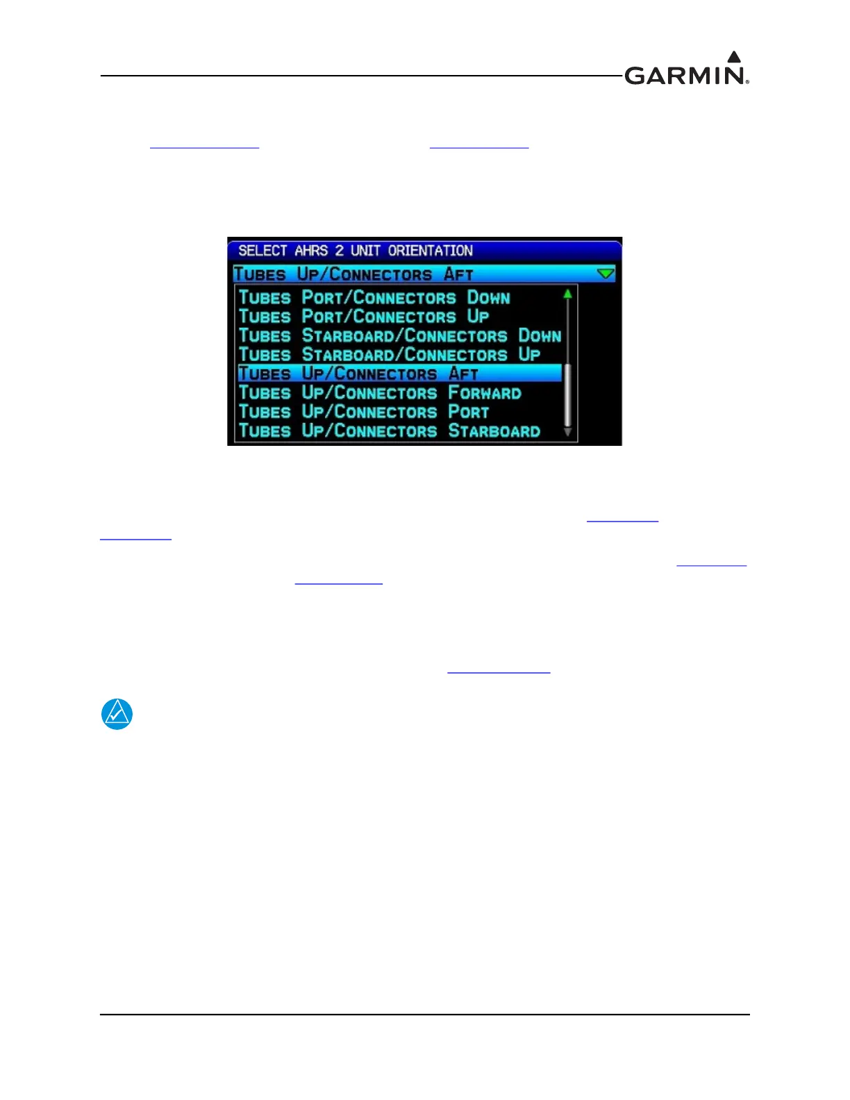
Figure 17-2 AHRS Orientation Selection
17.4.3 Unit Mounting
For final installation and assembly, refer to the outline and installation drawing Figure 17-4
and
Figure 17-5
of this manual.
1. Mount the unit to a suitable mounting location using the hardware in the connector kit (Table 17-4)
per the requirements in Section 17.4.2
.
2. Assemble the wiring harness and backshell connectors
3. Assemble the pneumatic hoses and connectors.
4. Connect backshell connector and hoses.
5. Connect CAN terminator to unit if required (see Section 2.3.1.3.3
).
NOTE
When mounting the GSU 25 to the airframe, it is important to make sure that fastening
hardware is tight for proper unit operation.
 Loading...


