190-01115-01 G3X™/G3X Touch™ Avionics Installation Manual
Rev. AV Page 21-25
21.3.5 RPM (Revolutions Per Minute)
21.3.5.1 Lycoming/Continental RPM Sensor Installation
The following two types of mechanical RPM sensors are supported:
UMA 1A3C-2, UMA 1A3C-4 - Standard mechanical tach drive sensors
The standard mechanical tach drive sensor is installed on the engine accessory case:
1.
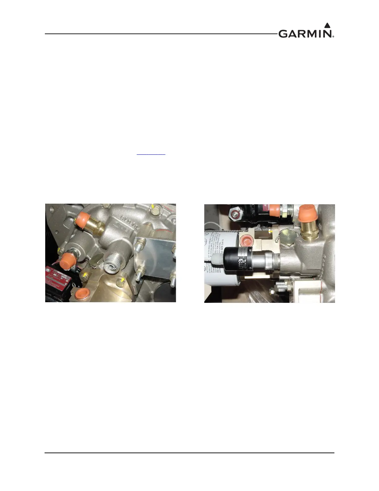
Remove the cap from the tachometer drive output (Figure 21-13) from the back of the engine.
2. Insert adapter tang into slotted keyway in sensor drive port.
3. Screw tach sensor onto threaded driver port, verify the adapter tang on the sensor aligns with the
slotted keyway in the drive port (
Figure 21-14
).
4. Connect the supplied connector to the appropriate inputs on the GEA 24/GSU 73 as referenced in
the G3X interconnects in Sec
tion 31. Secure the connector and wire assembly to an appropriate
location in the engine compartment to provide strain relief.
The body of the sensor unit can be offset slightly to eliminate potential interference with other engine
accessories. If the interference cannot be alleviated by offsetting the sensor directly, the builder may either
install a magnetic pickup sensor or use a short tachometer drive extension cable to remote mount the
sending unit to the engine mount (or other suitable location)
Figure 21-13 Tachometer Drive Output Figure 21-14 Installed Tachometer Sensor

 Loading...


