190-01115-01 G3X™/G3X Touch™ Avionics Installation Manual
Rev. AV Page 21-20
21.3.2.1 EGT Sensor Installation
General Installation Guidance – Garmin sensors kits include Alcor 86255 Type K thermocouple probes
(Garmin P/N 494-70001-00). Refer to Alcor EGT Installation Instructions (P/N 59180) for complete
installation details. Engine manufacturer’s guidance should be consulted and followed for proper location
of EGT probes.
Perform the following steps and refer to Figure 21-6
, Figure 21-7, and Figure 21-8 to install an EGT
sensor.
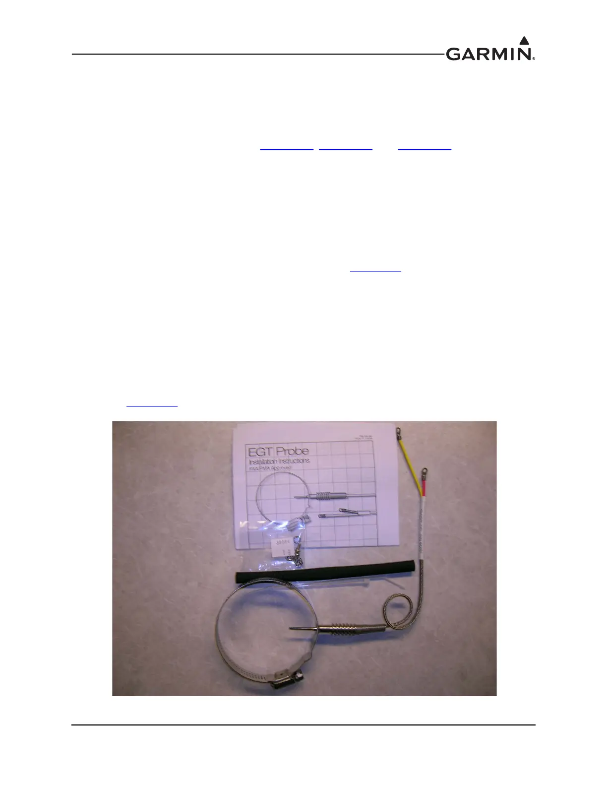
1. EGT probes (Figure 21-6) should optimally be mounted a minimum 2 inches and a maximum of 4
inches from the cylinder exhaust port flange on a flat portion of the exhaust tube. For highly
supercharged engines, the EGT probe should optimally be mounted a minimum 5 inches and a
maximum of 7 inches from the cylinder exhaust port flange on a flat portion of the exhaust tube.
To maintain consistent readings across cylinders, all probes should be mounted an equal distance
from the exhaust flanges.
2. Carefully center punch the probe hole locations so the external portion of the probe does not
interfere with any other parts of the engine or cowling (Figure 21-7
). It may be desirable to angle
the probes towards the rear of the engine to allow efficient wire routing back to the cockpit. If
angling the probes towards the rear of the engine, take care to make sure that sufficient clearance is
provided to service the spark plugs.
3. Carefully insert probe into the exhaust pipe and tighten the clamp snugly with screwdriver
(35 in-lbs torque max.).
4. Connect the EGT probes to the thermocouple extension wire. Provide strain relief for the assembly
by either fastening the probe leads to the valve covers with a clamp, or by tying the extension wire
to the intake tubes or other suitable location. A finger-sized loop should be provided to allow
appropriate strain relief, and care should be taken to make sure that no chafing of the wires occurs.
See Figure 21-8
for an example of an installed EGT probe.
Figure 21-6 EGT Package
 Loading...


