190-01115-01 G3X™/G3X Touch™ Avionics Installation Manual
Rev. AV Page B-4
NOTE
It is vital the front edge be squarely positioned against the flange. The GMU 22 rack
alignment points are based on the mount being perpendicular to the flange. The inner
edge should be aligned with the centerline on the fuselage.
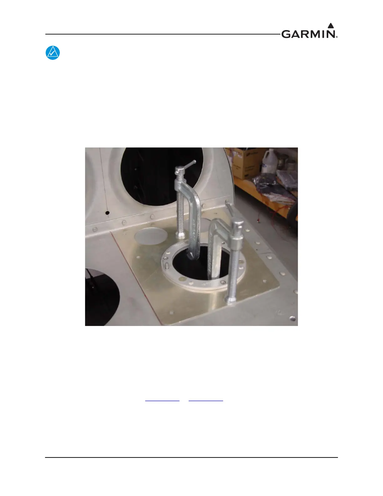
4. SECURELY clamp the mounting bracket to the aft deck so that no movement occurs with the front
edge flush with the vertical portion of the F-714 aft deck.
5. Drill the six attach points with a #30 drill bit.
6. Rivet the mounting bracket to the aft deck using AN470AD4 or LP4-3 rivets. Alternatively, the
builder may elect to install the mounting bracket with non-ferrous fasteners (screws, washers, and
nuts).
Figure B-2 RV-7/9 GMU 22 Mounting Bracket on the F714 Aft Deck
B.2.2 RV-6/8/10
In RV-6/8/10 aircraft, the GMU magnetometer is frequently mounted on a rigid aluminum shelf suspended
between the aft fuselage longerons, midway between the baggage bulkhead and empennage. If this
location is used, make sure the seat belt cables and attachment hardware are not magnetized. The wingtip
can be used as an alternate GMU magnetometer mounting location for RV aircraft. Provide adequate
separation from steel aileron counterweights, transmitting antennas, and lighting fixtures, and follow the
wingtip light wiring guidance for in Section 13.4
or Section 14.4.
B.2.3 RV-12/14
Consult Van’s Aircraft for information regarding GMU magnetometer mounting brackets for RV-12/14
aircraft.

 Loading...


