190-01115-01 G3X™/G3X Touch™ Avionics Installation Manual
Rev. AV Page 7-1
7 GEA™ 24 ENGINE INTERFACE MODULE INSTALLATION
NOTE
References to the GEA 24 throughout this manual apply equally to the GEA 24B except
where specifically noted.
This section contains general information as well as installation information for the GEA 24. Use this
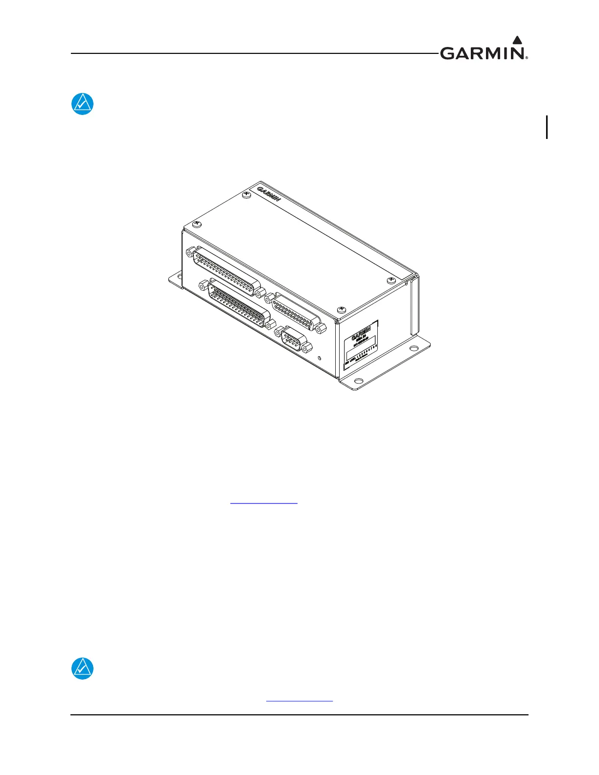
section to mount the GEA 24 unit.
Figure 7-1 GEA 24 Unit View
7.1 Equipment Description
The GEA 24 is an input/output system used to monitor and power engine and airframe sensors for the
Experimental – Amateur Built (E-AB) and Light Sport Aircraft (LSA) markets. In a G3X™ avionics or
G3X Touch™ avionics system, two GEA 24 units may be installed to monitor and display engine data for
twin-engine aircraft, or single-engine aircraft with more than six cylinders. The second GEA 24 must be
configured as EIS #2 as described in Section 23.4.16
.
• 9 pin network-power connector
• 50 pin miscellaneous connector for airframe sensors
• 25 pin thermocouple input connector
• 37 pin miscellaneous connector (for airframe sensors) will provide for the following input/output
functionality:
◦ Configure analog, digital, and discrete I/O capability
◦ Output digital measurement of analog input resistive sensors
◦ Output digital measurement of analog input voltages
◦ Output digital state of discrete input sources
◦ Output frequency measurement of digital input sources
◦ Control of discrete annunciator outputs
NOTE
If a GEA 24 is installed in a system that also includes a GSU 73, the GEA 24 must be
configured as EIS #2 as described in Section 23.4.16
.
GEA 24 UNIT
011-02848-00
J243
J242
J244
J241

 Loading...


