190-01115-01 G3X™/G3X Touch™ Avionics Installation Manual
Rev. AV Page 23-13
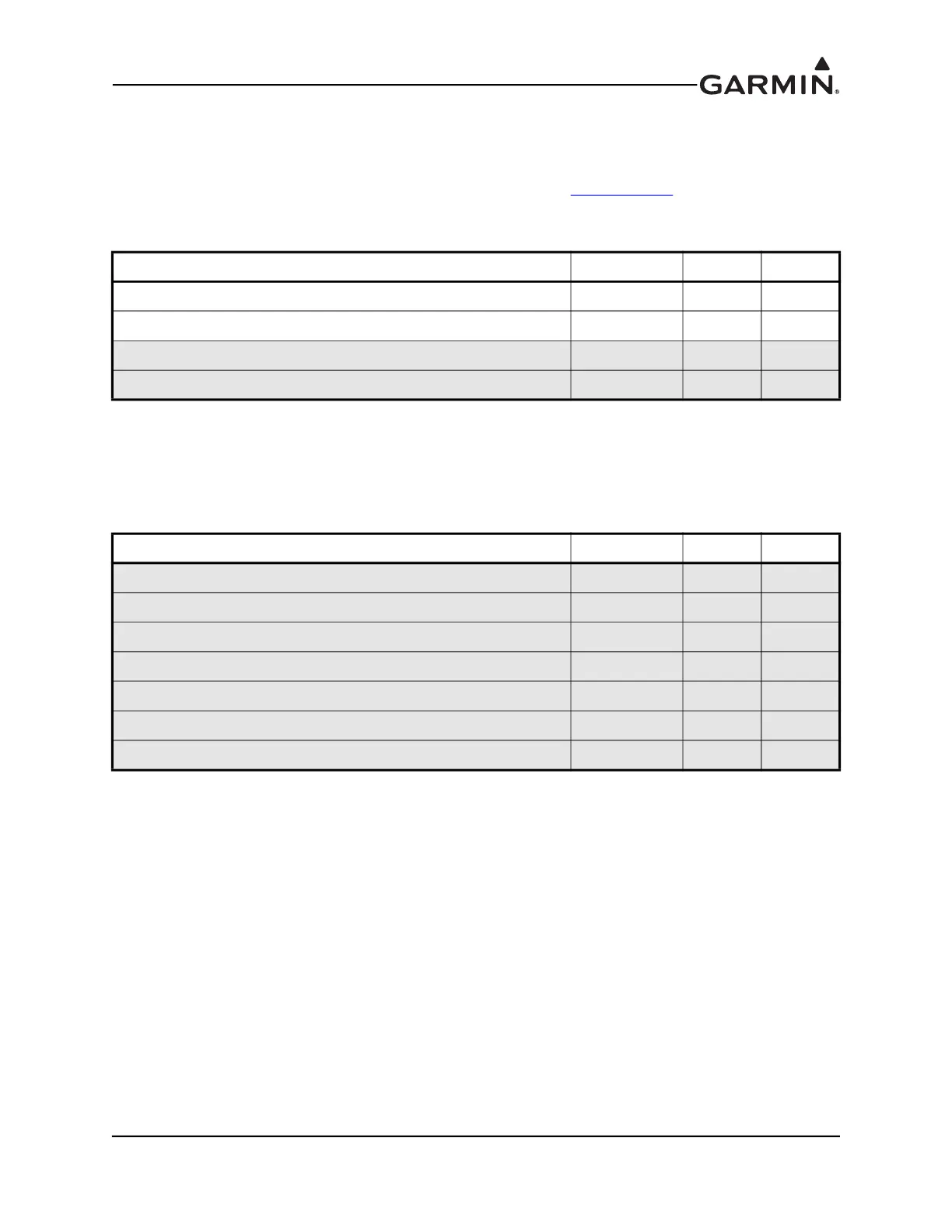
23.2.5 CAN Bus
The CAN Bus conforms to the BOSCH standard for Controller Area Network 2.0-B, and complies with
ISO 11898. Pins 9 and 21 are used to terminate the CAN bus. To terminate the CAN bus at the
GAD 29/29B/29C/29D short the pins (9 and 21) together. Refer to Section 2.3.1.3
for details on
configuring and terminating the CAN bus. The CAN bus on J291 shall be used for communications
between G3X LRUs.
23.2.6 Autopilot Heading/Course (GAD 29B/29D only)
The GAD 29B/29D can provide analog heading and course error outputs to non-Garmin analog autopilots.
In the case of an AC autopilot, the GAD 29B/29D has an AC REFERENCE signal input.
Pin Name Connector Pin I/O
CAN HI J291 1 I/O
CAN LO J291 2 I/O
CAN TERM 1 J292 9 --
CAN TERM 2 J292 21 --
Pin Name Connector Pin I/O
AC REFERENCE HI J292 1 In
AC REFERENCE LO J292 2 In
HDG/CRS VALID J292 3 Out
HEADING ERROR HI J292 8 Out
HEADING ERROR LO J292 14 In
COURSE ERROR HI J292 15 Out
COURSE ERROR LO J292 20 Out

 Loading...


