190-01115-01 G3X™/G3X Touch™ Avionics Installation Manual
Rev. AV Page 23-48
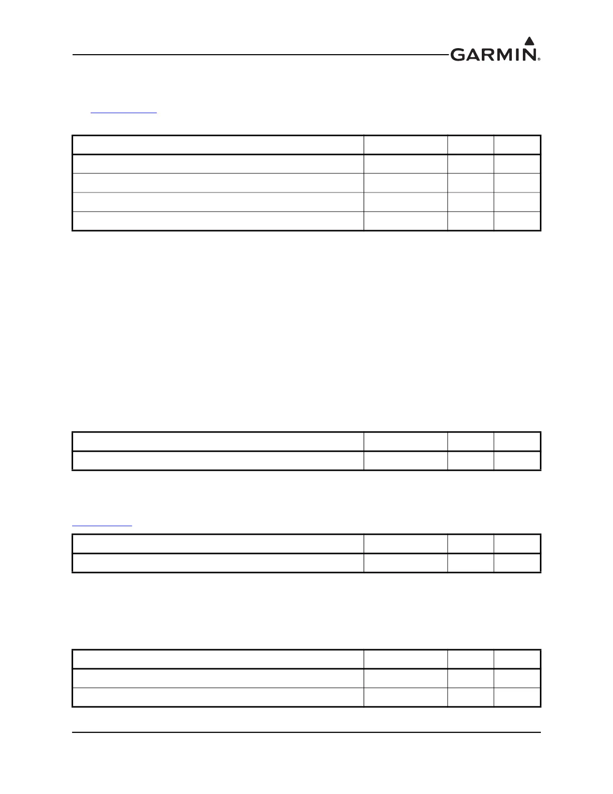
23.9.3 CAN Bus
The G3X CAN bus conforms to the BOSCH standard for Controller Area Network 2.0-B and ISO 11898.
See Section 2.3.1.3
for details. To enable the internal CAN terminator when the GMC 507 is installed at
one of the two ends of the CAN bus, a wire must be installed to short pin 6 to pin 8.
23.9.4 Lighting
The GMC 507 supports two internal backlighting buses, one for the mode (indicator) lights above the
buttons, and one for the button text, panel text, and knob backlighting.
Mode Indicator Backlighting - The lighting level for the mode lights (indicator triangles) above the buttons
is controlled by the photocell only, and is not affected by the lighting bus input (pins 11 and 12). This
makes sure the mode selection lights on the panel are always visible (and are independent of the externally
applied lighting bus).
Button Text, Panel Text, and Knob Backlighting - The GMC 507 can be installed to use either the built-in
photocell or the 14V lighting bus input for backlight control of the button text, panel text, and knob
backlighting. The photocell controls all backlighting when the lighting bus input is below 1.4VDC (or
unconnected). If the lighting bus input voltage is greater than 1.4VDC, the GMC 507 uses the lighting bus
input voltage (1.4VDC-28.0VDC range) as a reference voltage (not power source) to adjust the
backlighting for these items.
23.9.5 TO/GA Discrete In
Provides an active low discrete input which may optionally be connected to a TO/GA button, see
Figure 24-1.8
.
23.9.6 Unit ID
Leave pins 1 and 2 open to configure as GMC 507 #1. Strap pins 1 and 2 together to configure as
GMC 507 #2. GMC 507 #2 will act as a remote controller only, monitoring is turned off and the AP
disconnect and TO/GA inputs are left unconnected.
Pin Name Connector Pin I/O
CAN HI J7001 3 I/O
CAN LO J7001 4 I/O
CAN BUS TERM 1 J7001 8 --
CAN BUS TERM 2 J7001 6 --
Pin Name Connector Pin I/O
LIGHTING BUS HI J7001 11 In
Pin Name Connector Pin I/O
TO/GA DISCRETE IN J7001 10 In
Pin Name Connector Pin I/O
UNIT ID 1 J7001 1 In
UNIT ID 2 J7001 2 In

 Loading...


