190-01115-01 G3X™/G3X Touch™ Avionics Installation Manual
Rev. AV Page 1-9
1.5.4 SD Card
An SD Card is required to be used as a DataCard. Garmin recommends a 2 GB SanDisk® brand SD card
for GDU 37X units, and an 8 GB SanDisk® brand SD card for GDU 4XX units. SD or SDHC cards up to
32 GB using the FAT32 file format are supported, SDXC and SDUC cards are not supported. See
Appendix H.5.1
, Section 30.5.1, and Section 31.3.1 for detailed information.
1.5.5 Non-Magnetic Tools (GMU Units)
Use of non-magnetic tools (e.g. beryllium, copper, or titanium) is recommended when installing or
servicing the GMU magnetometer. Do not use a screwdriver that contains a magnet when installing or
servicing a magnetometer.
1.5.6 Pneumatic Hoses and Connectors
Air hoses and fittings are required to connect pitot and static air to the ADAHRS (GSU 25/73). The
ADAHRS (GSU 25/73) has a female 1/8-27 ANPT fitting for each pitot and static port. Use appropriate
aircraft fittings to connect to pitot, static, and Angle of Attack (AOA on GSU 25 only) system lines.
1.5.7 GAD 27/GAD 29/GEA 24/GPS 20A/GSU 25 Mounting Hardware
If the installer does not use the applicable installation kit, an example of alternate mounting hardware is:
(4 ea.) #10-32 pan or hex head screws.
1.5.8 GAP 26 Mounting Hardware
The materials listed in Table 1-9 are required to assemble and mount the GAP 26:
1.5.9 GMU 11 Mounting Materials
The following materials (or equivalents) required to install the GMU 11 in a non-metallic wingtip:
• Tinned copper flat braid, 1/4”, QQB575F36T0250
• Electrical tie-down strap, adjustable, MS3367- (1, 2, or 7)-X
• Terminal lug, #10, uninsulated, MS25036-108
• Terminal stud, #10
• Terminal lug, #8, uninsulated, MS25036-153
1.5.10 GSU 73 Mounting Hardware
An example of GSU 73 mounting hardware is: #10-32 pan or hex head screw (4 ea.) and #10-32 self-
locking nut (4 ea). (see Appendix F.5.13
)
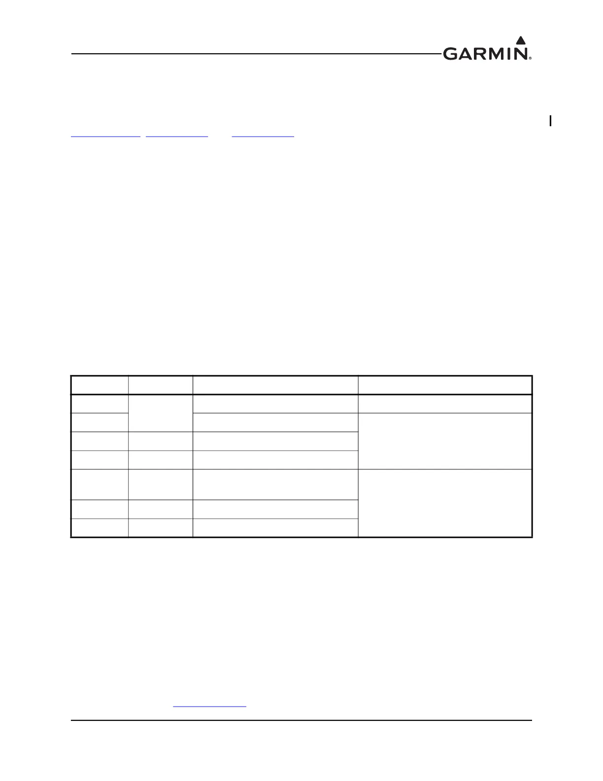
Table 1-9 GAP 26 Mounting Hardware
Quantity Item Part Number Notes
4
Screw #6
MS51957-26 Mount tube to probe
2 MS51957-32
Mount tube to mount bracket2 Washer #6 NAS1149CN632R
2 Nut #6 MS21044C06
4 Screw #8
MS24693-CXX (Countersunk) OR
MS51957-XX (Pan Head)
Mount bracket to inspection panel
4 Washer #8 NAS1149CN832R
4 Nut #8 MS21044C08

 Loading...


