COPYRIGHT
©
2000 CANON INC. 2000 2000 2000 2000 CANON iR5000/iR6000 REV.0 JULY 2000
CHAPTER 1 BASIC OPERATION
1-2 R
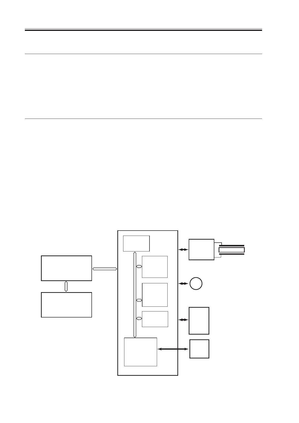
CCD/AP
PCB
ADF
Scanner
motor
Reader controller PCB
Controller unit
Printer unit
Inverter
PCB
LA2
M3
IC5021
(IPC comm-
unication 2
)
IC5016
(ROM)
IC5025
(CPU)
IC5008
IC5009
(RAM)
IC5027
(EEPROM)
F01-202-01 Major PCBs
T01-202-01 List of Control Items
2. Outline of Electrical Circuitry
2.1 Outline
The major mechanisms of the reader unit are controlled by the CPU on the reader control-
ler PCB.
The functions of the major ICs are as indicated in the following table.
2.2 Reader Controller PCB
Name
CPU
RAM
EEP-ROM
ROM
Description
• Controls the sequence of scanner
operations.
• Controls the original size detection
mechanism.
• Controls the CCD.
• Controls the communications with
the ADF.
• Stores service mode data.
• Stores user mode data.
• Stores control data.
• Backs up RAM data.
• Stores control programs.
• Controls the scanning lamp.
• Controls shading correction.
• Controls service mode.
• Controls the communications with
the main controller.
Download Free Service Manual at http://printer1.blogspot.com
 Loading...


