COPYRIGHT
©
2000 CANON INC. 2000 2000 2000 2000 CANON iR5000/iR6000 REV.0 JULY 2000
CHAPTER 3 LASER EXPOSURE SYSTEM
3-9 P
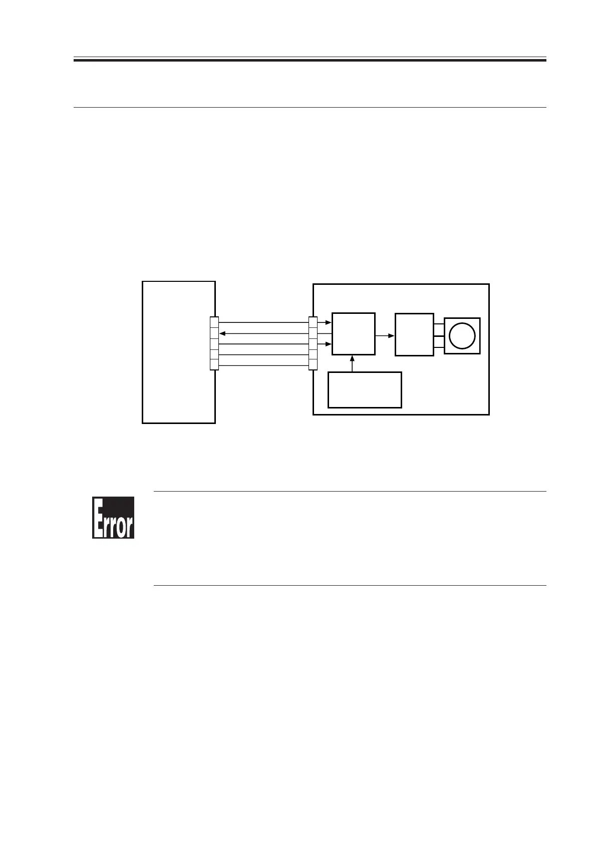
4. Controlling the Laser Scanner Motor
4.1 Outline
The following signals are used to control the laser scanner motor:
[1] Laser scanner motor drive signal. When ‘1’, the laser scanner motor is turned on (i.e.,
turning on/off the motor).
[2] Laser scanner motor speed switch signal. When ‘0’, the motor is rotated at full speed;
when ‘1’, in-wait rotation (i.e., switching the speed).
[3] Laser scanner motor ready signal. When ‘0’, the laser scanner motor is rotated at a con-
stant speed (constant speed rotation control).
F03-401-01 Functional Block Diagram
E110
It is indicated under the following conditions:
[1] If the laser scanner motor ready signal (LMRDY*) goes ‘1’ when the
motor is rotating.
[2] If the laser scanner motor ready signal (LMRDY*) does not go ‘0’
within a specific period of time.
LMSPSEL [2]
J116
J2511
(J1)
+24V
GND
LMRDY
*
[3]
LMON [1]
Laser scanner
motor
DC controller
PCB
M15
2
3
4
5
1
4
3
2
1
5
Speed
control
circuit
Reference
pulse generation
circuit
Motor
driver
Download Free Service Manual at http://printer1.blogspot.com
 Loading...


