COPYRIGHT
©
2000 CANON INC. 2000 2000 2000 2000 CANON iR5000/iR6000 REV.0 JULY 2000
CHAPTER 2 MAIN CONTROLLER
2-8 S
2. Digital Image Processing
2.1 Outline
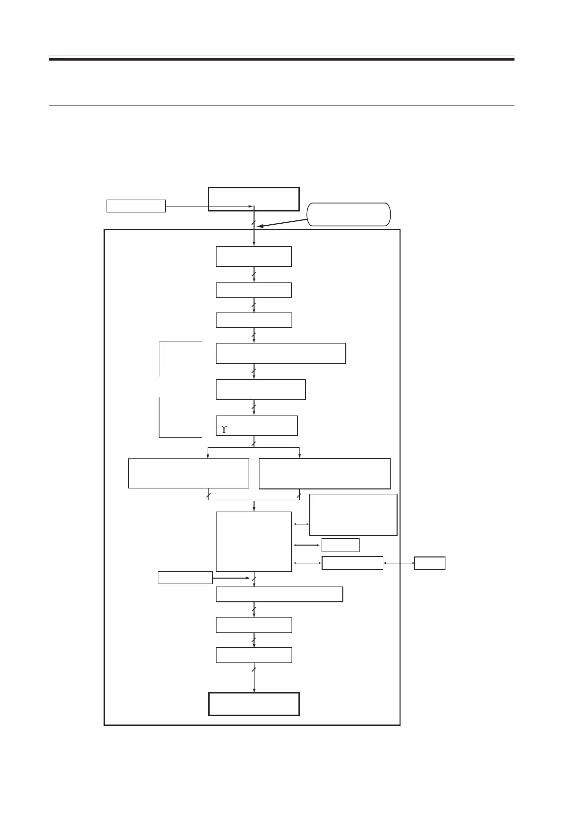
The machine’s digital image processing and control of the image memory is performed by
the main controller PCB. The following is a block diagram showing digital image process-
ing:
F02-201-01
8
Reader unit
Image data
after shading
Editing
Density conversion
(LUT)
Binary processing
(error division; text,
text/photo, print photo)
Image memory
control
Binary processing
(dither screen; print photo)
8
Density correction
(
¡
conversion)
8
8
8
Edge emphasis
1
Compression/
decompression,
rotation, enlargement/
reduction
SDRAM
I/O control
HDD
Image server
4 or 2
Thickening
4 or 2
1
Smoothing
1
Binary-binary density conversion
Printer unit
Print PG
1
8
8
Enlargement/reduction
(main scanning direction)
Density adjustment
(F-value conversion)
Luminance/density
conversion (LOG conversion)
Reader PG
Download Free Service Manual at http://printer1.blogspot.com
 Loading...


