COPYRIGHT
©
2000 CANON INC. 2000 2000 2000 2000 CANON iR5000/iR6000 REV.0 JULY 2000
CHAPTER 7 EXTERNALS AND CONTROLS
7-1 P
1. Control Panel
1.1 Outline
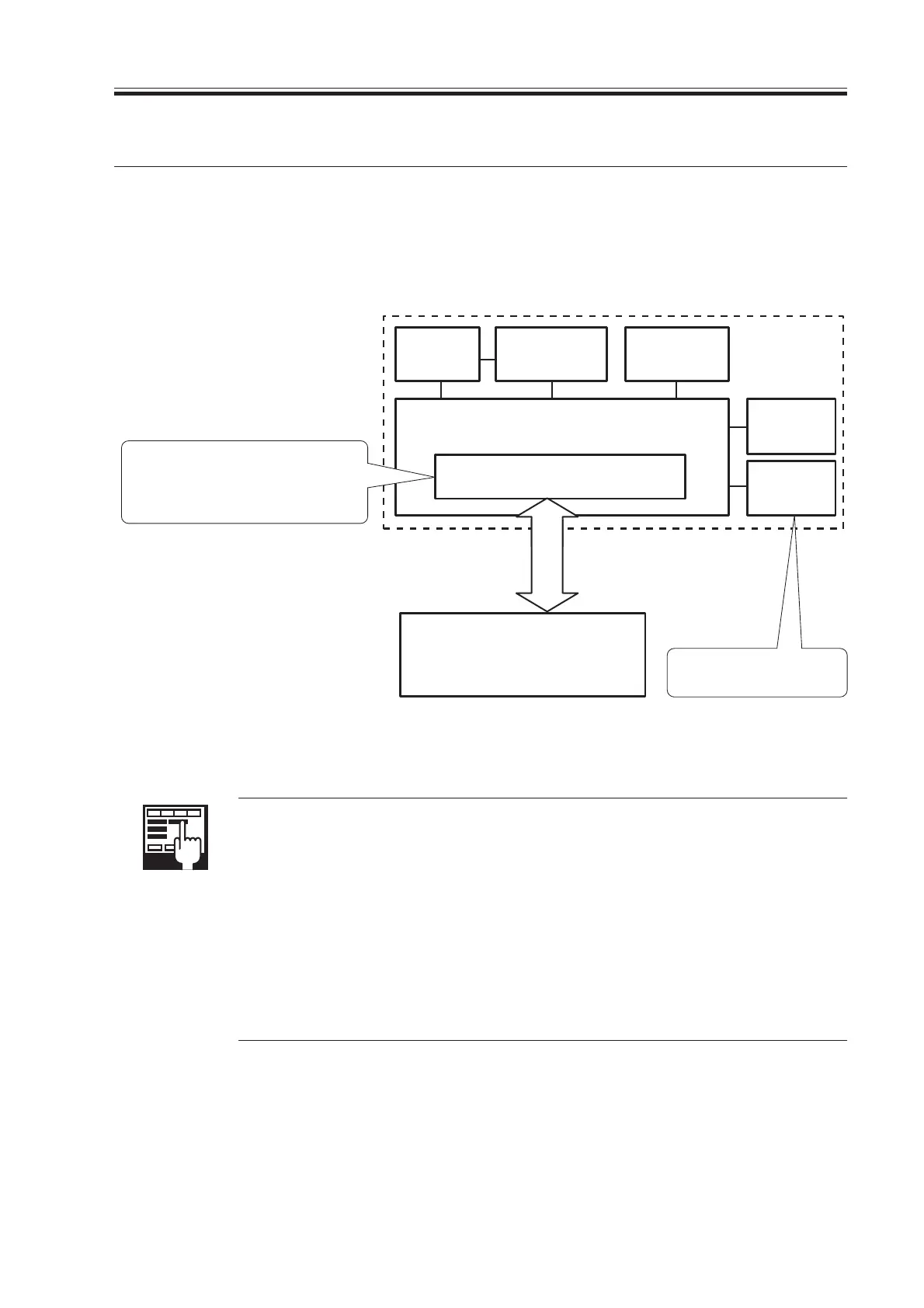
The machine’s control panel consists of the following PCBs and a touch panel (LCD) ca-
pable of display at a resolution of 320×240 dots:
F07-101-01
COPIER>FUNCTION>PANEL>LCD-CHK
Used to check missing dots in the LCD display.
COPIER>FUNCTION>PANEL>LED-CHK
Used to start a check on the activation of LEDs in the control panel.
COPIER>FUNCTION>PANEL>LED-OFF
Used to end a check on the activation of LEDs in the control panel.
COPIER>FUNCTION>PANEL>KEY-CHK
Used to start a check on key inputs.
COPIER>FUNCTION>PANEL>TOUCHCHK
Used to adjust the coordinates in the touch panel.
CPU
Control
panel
inverter PCB
LCD PCB
Control panel
PCB
(key & LED)
Control
panel power
switch PCB
LCD contrast
adjustment
PCB
Control panel CPU PCB
Control panel
· Key input monitor: keypad,
function key
· Buzzer control
· Control panel LED activation
Adjusts the contrast of the
LCD.
Controller unit
Download Free Service Manual at http://printer1.blogspot.com
 Loading...


