COPYRIGHT
©
2000 CANON INC. 2000 2000 2000 2000 CANON iR5000/iR6000 REV.0 JULY 2000
CHAPTER 4 IMAGE FORMATION SYSTEM
4-29 P
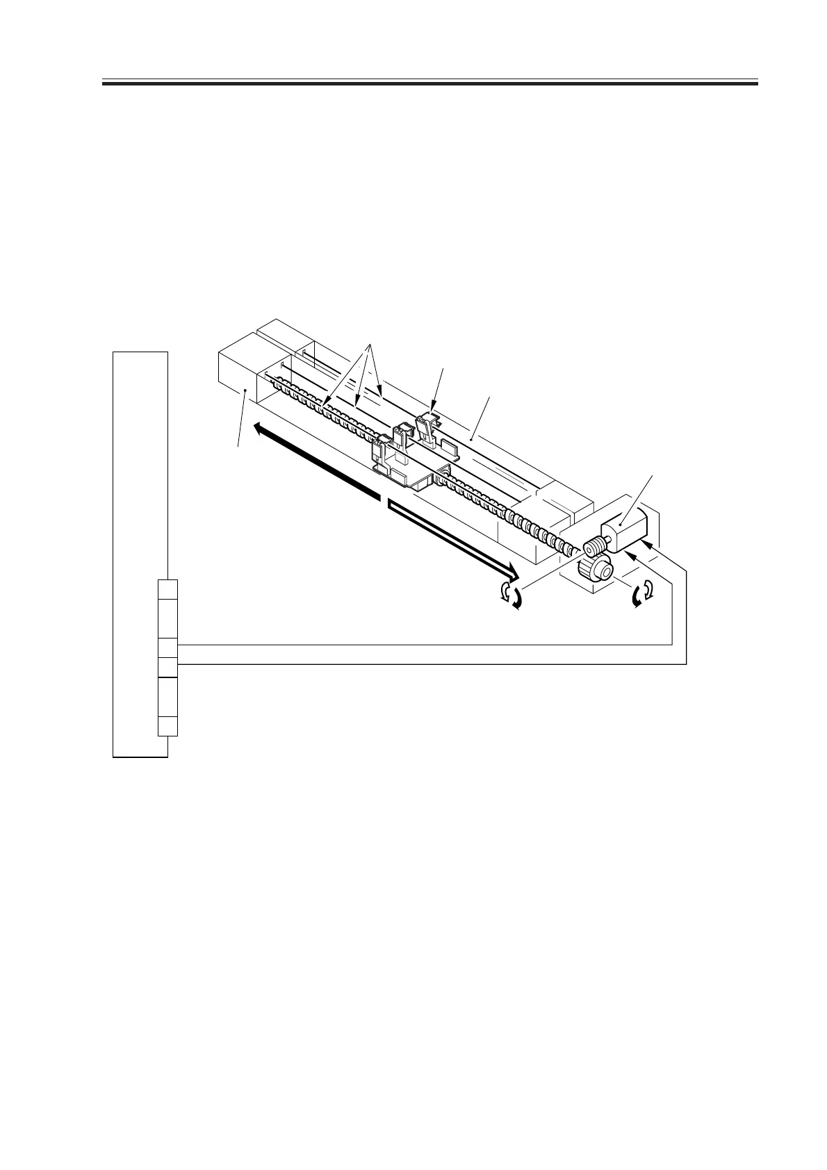
3.5.3 Cleaning Mechanism for the Transfer Charging Assembly
The transfer charging wire is cleaned at such times as follows, and its control mechanism
is constructed as follows:
Timing of Cleaning
1. If the temperature of the fixing roller is 100°C or lower at power-on.
2. When cleaning is executed in user mode.
3. At the end of making 2,000 prints*1 after cleaning
*1: Default; may be changed in service mode: COPIER>OPTION>BODY>W-CLN-P.
F04-305-03
The system uses the following signals:
[1] transfer charging wire cleaning motor CW drive signal; when ‘1’, the wire cleaner
moves to the rear.
[2] transfer charging wire cleaning motor CCW drive signal; when ‘1’, the wire cleaner
moves to the front.
DC controller PCB
8
7
20
1
T/SCLM1 [1]
J106A
Transfer/separation charging
wire cleaning motor (M8)
Rear
Front
Separation
charging
assembly
Transfer charging assembly
Wires
Wire cleaner
T/SCLM2 [2]
••• •••
Download Free Service Manual at http://printer1.blogspot.com
 Loading...


