COPYRIGHT
©
2000 CANON INC. 2000 2000 2000 2000 CANON iR5000/iR6000 REV.0 JULY 2000
CHAPTER 4 IMAGE FORMATION SYSTEM
4-5 P
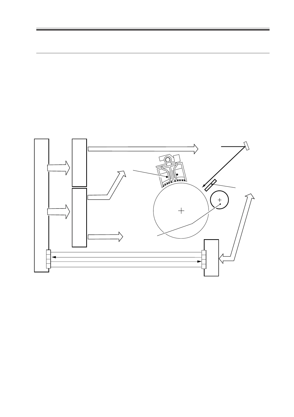
F04-201-01 Block Diagram of the Control System
The signals used are as follows:
[1] POT-DT: drum surface potential measurement value.
[2] POT -ON: when ‘1’, the potential sensor turns on.
2. Potential Control
2.1 Outline
The functions and control mechanisms related to the potential control system are as fol-
lows:
1. Controlling potential for the copier/printer
2. Correcting power (APC, i.e., Auto Power Control)
3. Determining primary current (VD control)
4. Determining laser output (VL control)
5. Determining developing bias (DC; VDC control)
The control system related to potential control is designed as follows:
Primary charging wire
Potential sensor
Laser light
Developing
cylinder
DC controller PCB
Laser driver PCB
High-voltage PCB
Potential control PCB
Control signal
Control signal
Detention signal
J103
J3
1
2
3
4
B1
B2
B3
B4
0V
24V
POT-DT
POT-ON
[1]
[2]
Determining developing bias(DC)
Determining laser output
Determining primary current
Download Free Service Manual at http://printer1.blogspot.com
 Loading...


