COPYRIGHT
©
2000 CANON INC. 2000 2000 2000 2000 CANON iR5000/iR6000 REV.0 JULY 2000
CHAPTER 6 FIXING SYSTEM
6-37 P
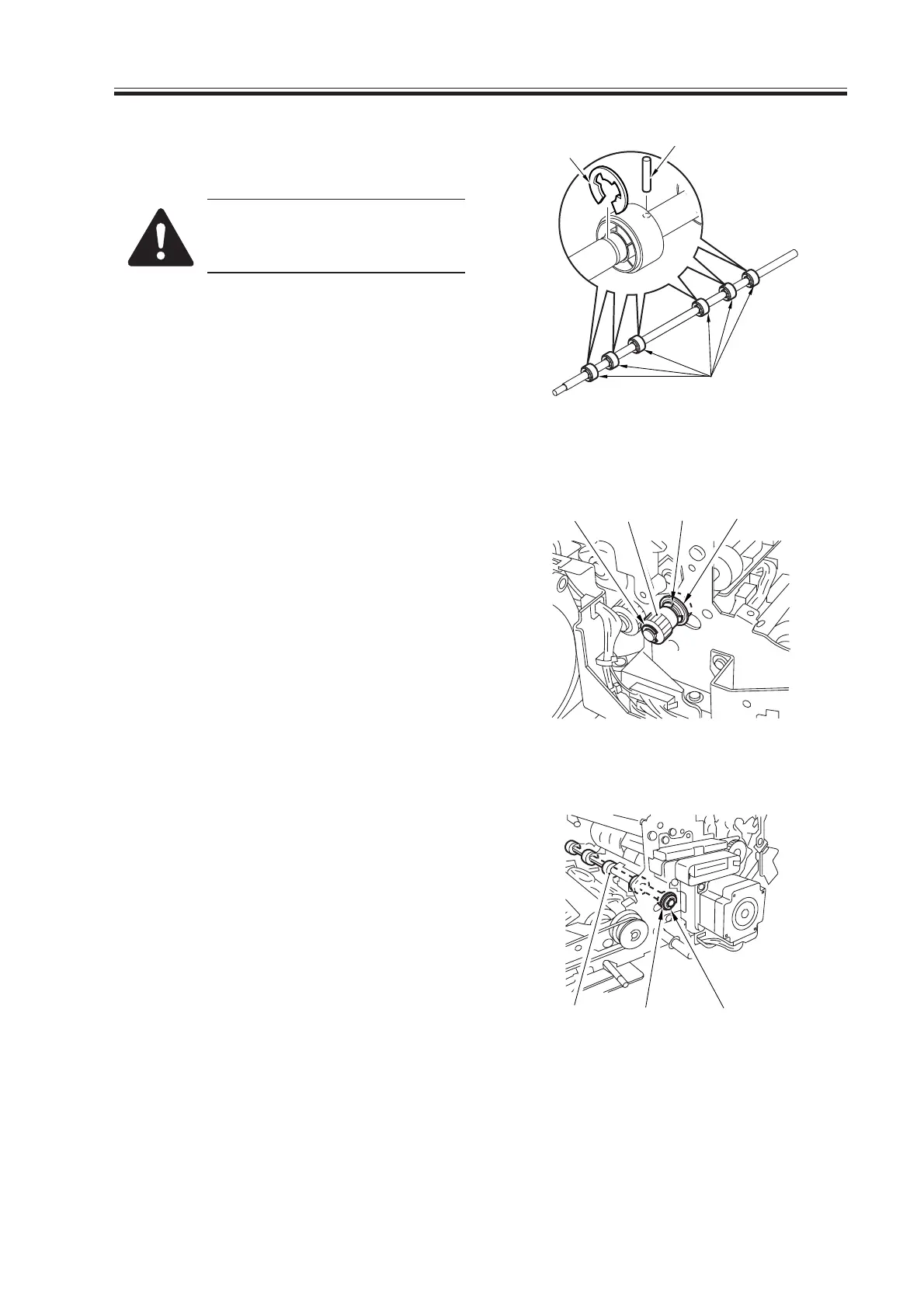
5) Remove the six E-rings [9] of the roll-
ers, and detach the six rollers [11].
Each roller is equipped with a
parallel pin [10]. Take care not
to drop it.
F06-406-04
4.6.2 Removing the Internal Delivery Roller
1) Remove the fixing assembly from the
machine.
2) Remove the lower separation claw plate.
3) Remove the two E-rings [1] at the front,
and remove the gear [2] and the bearing
[3].
F06-406-05
4) Remove the E-ring [4] at the rear, and
remove the bearing [5] and the internal
delivery roller [6].
F06-406-06
[11]
[9]
[10]
[1] [2] [1]
[3]
[6] [5]
[4]
Download Free Service Manual at http://printer1.blogspot.com
 Loading...


