COPYRIGHT
©
2000 CANON INC. 2000 2000 2000 2000 CANON iR5000/iR6000 REV.0 JULY 2000
CHAPTER 3 LASER EXPOSURE SYSTEM
3-4 P
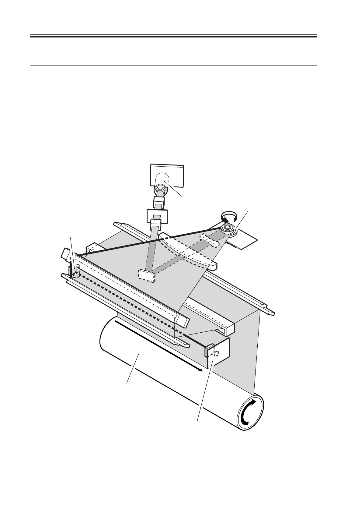
2. Generating Sync Signals
2.1 Outline
The BD signal used to synchronize video signals for laser scanning direction is generated
by the BD PCB with reference to the laser beam reflected by the BD mirror, mounted along
the path of the laser beam.
The CCD/AP PCB reads image signals from the CCD, and sends them to the controller
unit. The controller unit performs image processing, and the signals are sent to the laser
driver PCB as video signals through the DC controller PCB; they are then sent to the laser
unit as laser intensity control signals in sequence.
F03-201-01 Construction of the Control System
12-facet polygon
mirror
Laser unit
BD mirror
Photosensitive drum
BD PCB
Download Free Service Manual at http://printer1.blogspot.com
 Loading...


