COPYRIGHT
©
2000 CANON INC. 2000 2000 2000 2000 CANON iR5000/iR6000 REV.0 JULY 2000
CHAPTER 4 IMAGE FORMATION SYSTEM
4-12 P
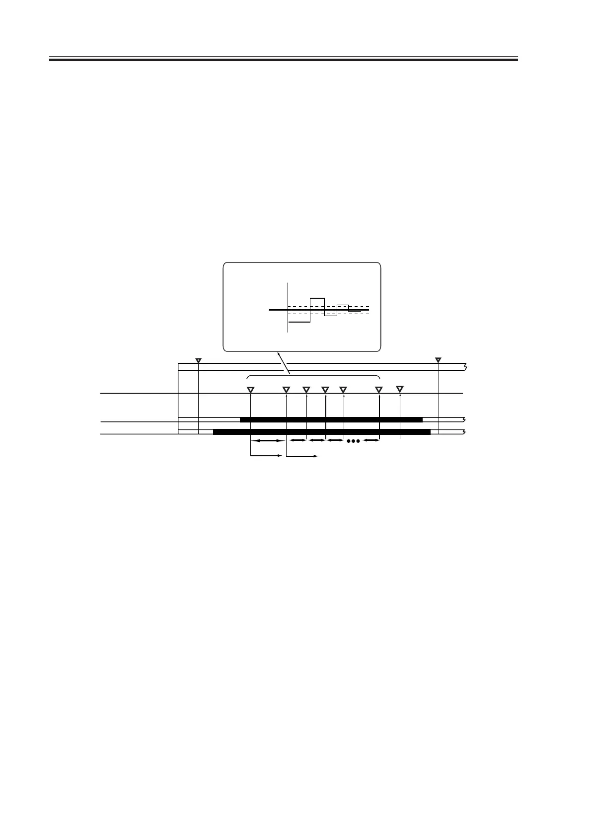
2.3 Determining the Laser Output
To measure the light area potential (VL1) after the power switch is turned on, the poten-
tial based on the previous laser output (LP0) is let to flow, and the surface potential of the
drum is measured by the potential sensor.
The DC controller PCB compares the surface potential of the drum against the target po-
tential; if the measured potential is ±6 V or higher, the potential of the laser output is cor-
rected, and the potential is corrected once again.
The potential is measured as many as eight times, and the laser output is corrected as
many as eight times. In addition, the developing bias for light area (VL2) is measured under
the corrective conditions used to determine the laser output (LP) needed for target potential.
F04-203-01
WMUPR
WMUP
STBY
200˚C
Potential sensor
Developing bias
(DC)
Laser
LP0
LP0 LP0 LP0
LP0
LP
VL1 VL1 VL1 TargetVL1
VL1
VL1
Correction control
sequence start
Fixing assembly
temperature 195˚C
VL1
+6V
-6V
VL1
VL1
VL1
Previous potential
Target VL1
Potential control
sequence start
VL2
Download Free Service Manual at http://printer1.blogspot.com
 Loading...


