COPYRIGHT
©
2000 CANON INC. 2000 2000 2000 2000 CANON iR5000/iR6000 REV.0 JULY 2000
CHAPTER 4 IMAGE FORMATION SYSTEM
4-59 P
7.4.2 Adjusting the Potential Sensor
The potential sensor and the po-
tential control PCB are adjusted
in a pair, requiring simultaneous
replacement.
1) Start service mode, and set ‘0’ to the
following to disable potential control:
COPIER>OPTION>BODY>PO-CNT.
2) Replace the potential control PCB.
3) Connect the connector of the potential
sensor to the connector of the machine.
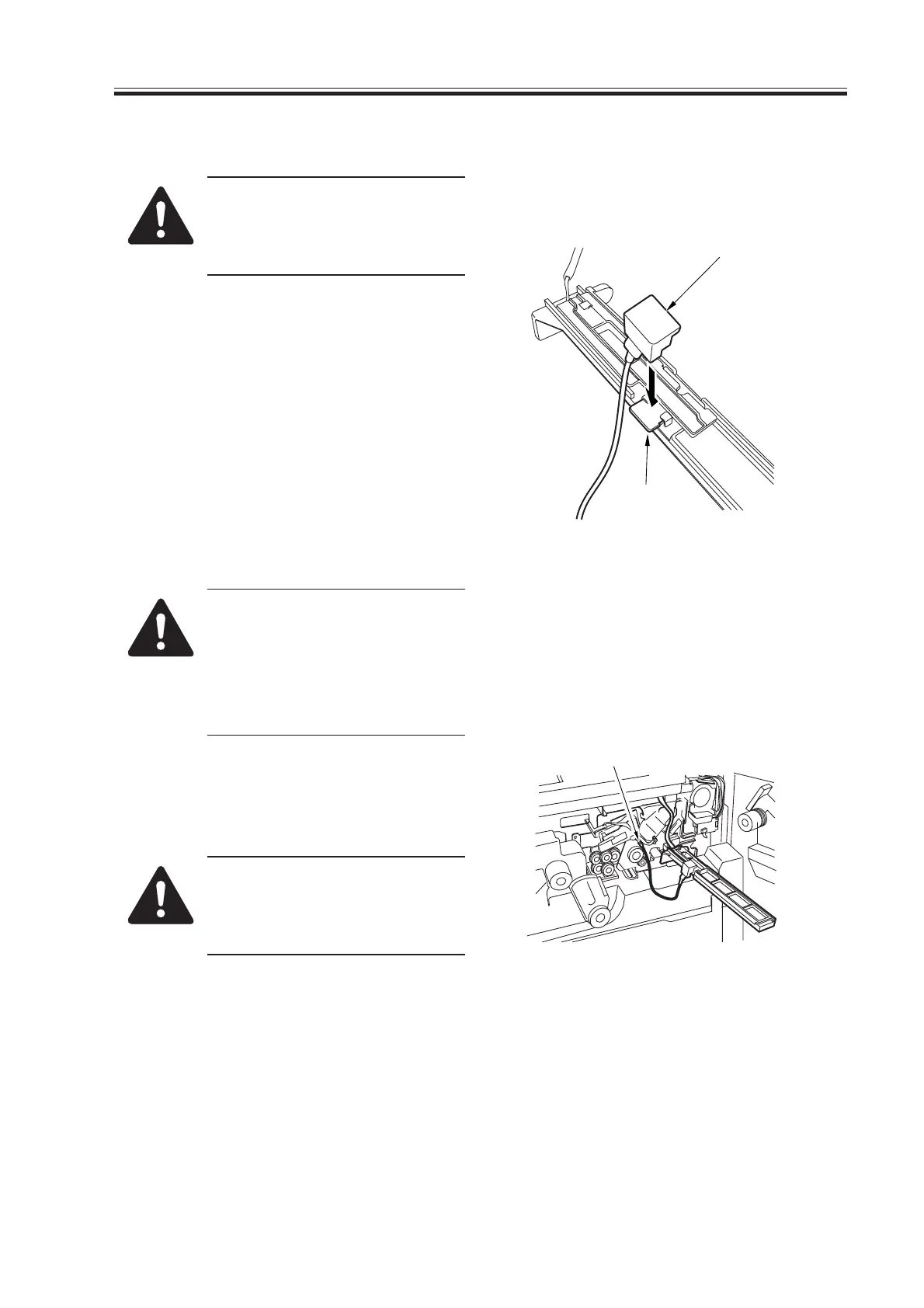
4) Fit the potential checking electrode
(FY9-3012) [2] to the potential sensor
[1].
F04-704-06
When fitting the checking elec-
trode to the potential sensor [2],
be sure that the magnet of the
checking electrode does not
come into contact with the po-
tential sensor cover.
5) Connect the clip [3] of the checking
electrode to the frame of the machine
(GND).
Be sure to keep the clip [3] fully
away from the sensor and not to
bring it in contact with the cover
of the sensor.
F04-704-07
[2]
[1]
[3]
Download Free Service Manual at http://printer1.blogspot.com
 Loading...


