COPYRIGHT
©
2000 CANON INC. 2000 2000 2000 2000 CANON iR5000/iR6000 REV.0 JULY 2000
CHAPTER 4 IMAGE FORMATION SYSTEM
4-39 P
4.3 Controlling the Developing Bias
The system used to control the developing bias serves the following functions:
[1] Controlling the DC bias to a specific level of voltage.
[2] Controlling the AC bias to a specific level of voltage.
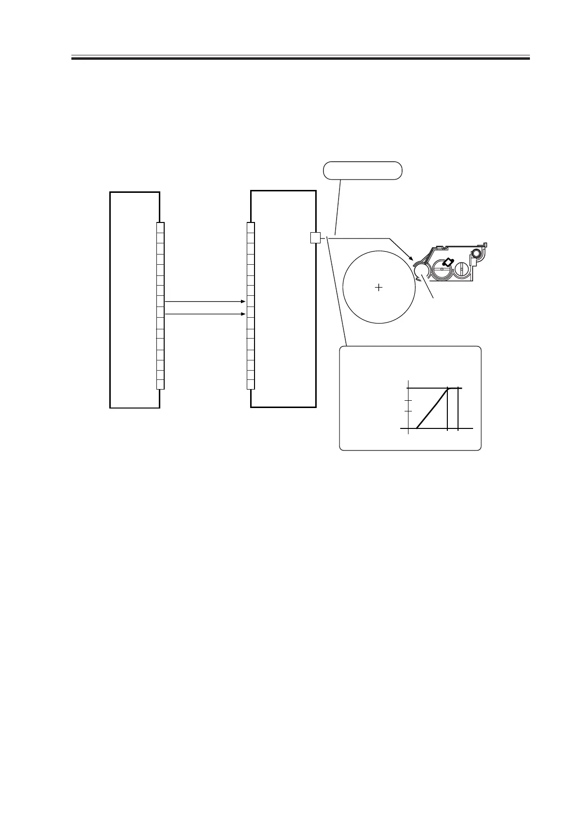
F04-403-01
The following signals are used:
[1] developing DC bias current control signal; if about 3 V or higher and lower than 11 V,
the output of developing DC bias current turns ON; if about 12 V or higher, it turns
OFF.
[2] developing DC bias remote signal; turns on/off the output of developing DC bias cur-
rent.
DC controller PCB
1
2
3
4
5
6
7
8
9
10
11
12
13
14
15
16
1
2
3
4
5
6
7
8
9
10
11
12
13
14
15
16
DEV-AC-REMOTE [2]
DEV-DC-CNT [1]
Developing cylinder
J4504
600V
Image area
Non-image area
The developing DC bias varies as
follows in keeping with the potential
of DEV-DC-CNT.
3V
11V 12V
DEV-DC-CNT
Developing DC bias
AC output 1500Vpp
High-voltage PCB
J102A
J4502
Download Free Service Manual at http://printer1.blogspot.com
 Loading...


