COPYRIGHT
©
2000 CANON INC. 2000 2000 2000 2000 CANON iR5000/iR6000 REV.0 JULY 2000
CHAPTER 7 EXTERNALS AND CONTROLS
7-23 P
[1]
[1]
[2]
[3] [3]
[3]
[4]
[5]
[6]
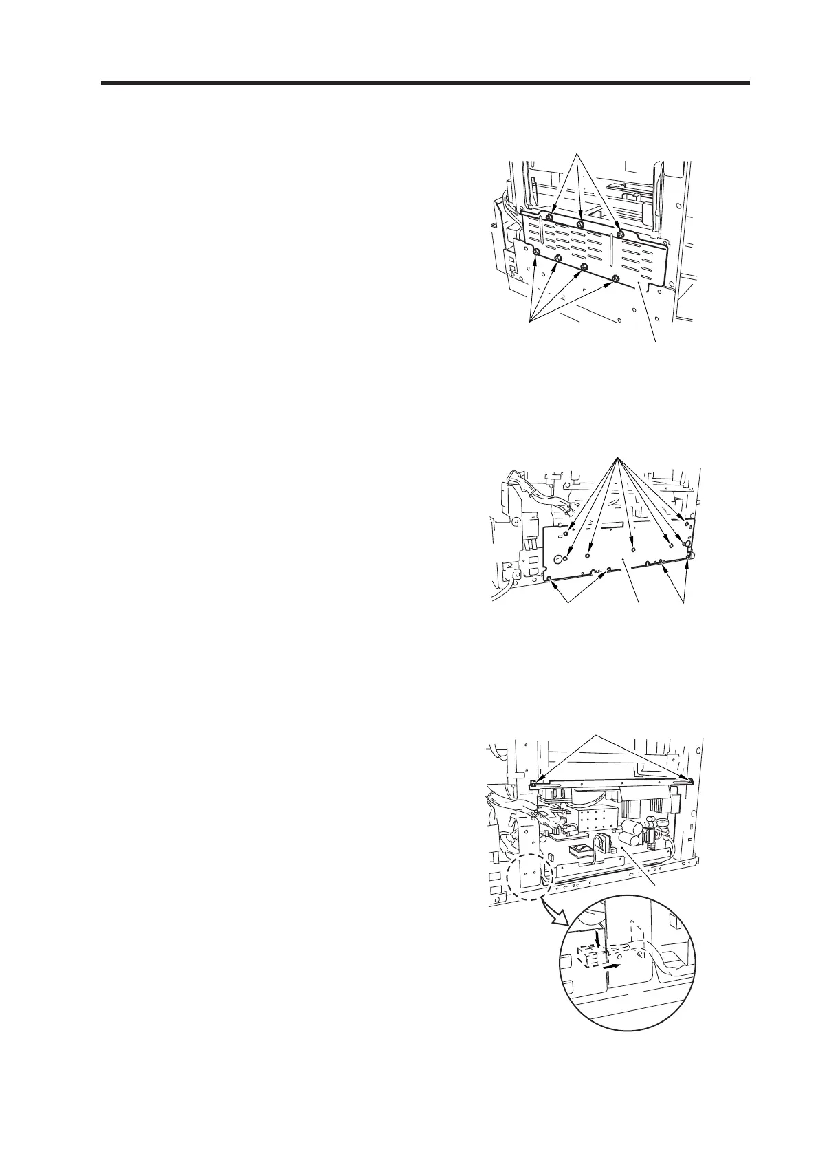
5.4.3 Power Supply PCB
1) Remove the left lower cover.
2) Remove the seven screws [1], and de-
tach the shielding plate [2].
F07-504-06
3) Remove the 11 screws [3], and detach
the power supply cover [4].
F07-504-07
4) Disconnect the 15 connectors, and re-
move the two screws [5]; then, detach
the power supply PCB [6].
F07-504-08
Download Free Service Manual at http://printer1.blogspot.com
 Loading...


