COPYRIGHT
©
2000 CANON INC. 2000 2000 2000 2000 CANON iR5000/iR6000 REV.0 JULY 2000
CHAPTER 7 EXTERNALS AND CONTROLS
7-24 P
[1]
[3]
[2]
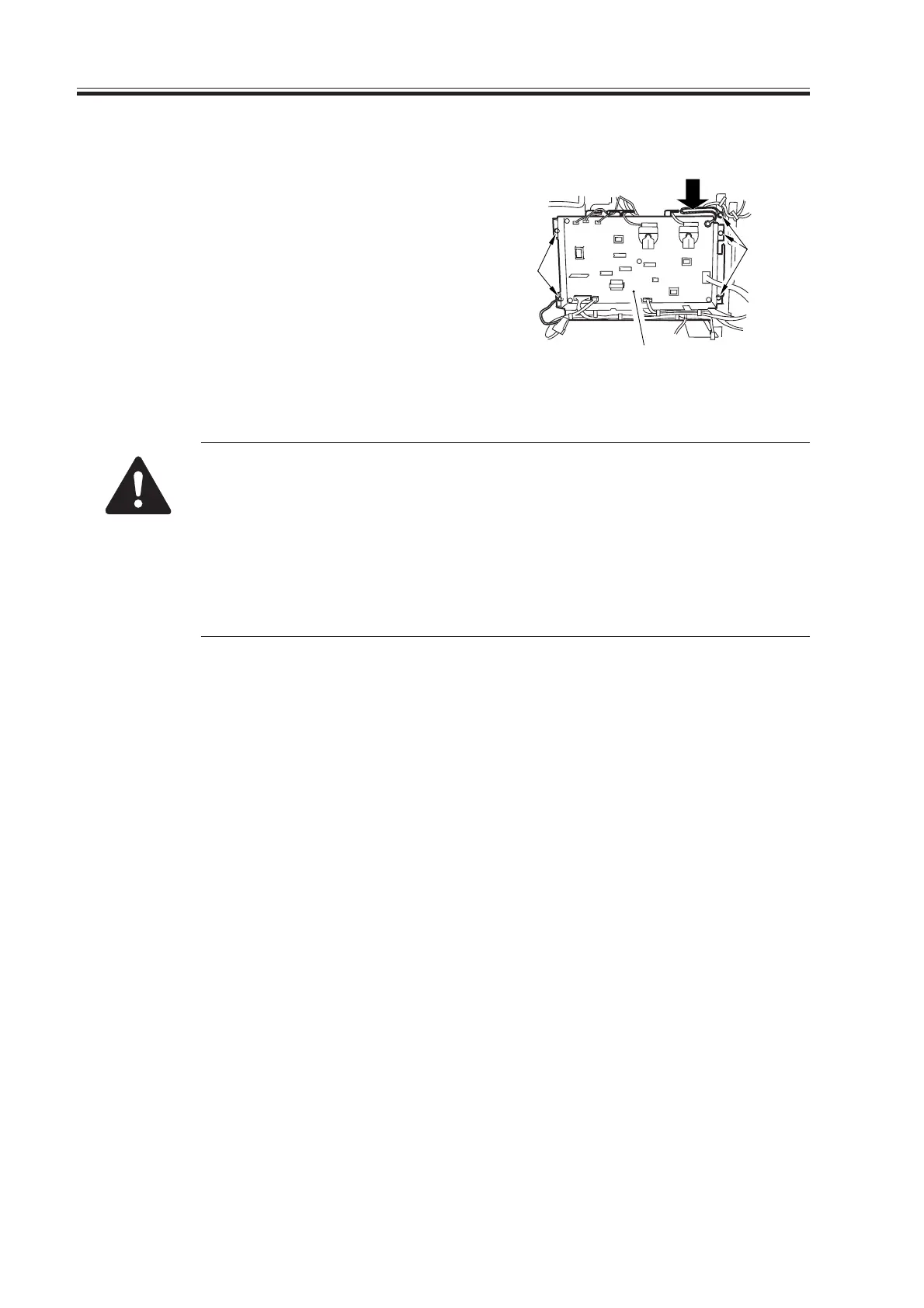
5.4.4 High-Voltage Power Supply PCB
1) Remove the rear lower cover.
2) Remove the five screws [1], and discon-
nect the nine connectors; then, detach
the high-voltage power supply PCB [2].
F07-504-09
When replacing the PCBs, keep the following mind:
• Be sure to enter the values indicated on the label attached to the new
PCB (indicated by an arrow [3]) in service mode by making the follow-
ing selections:
COPIER>ADJUST>HV-TR>H-PRE-TR
COPIER>ADJUST>HV-TR>HVT-TR
COPIER>ADJUST>HV-SP>HVT-SP
COPIER>ADJUST>DEVELOP>HVT-DE
Download Free Service Manual at http://printer1.blogspot.com
 Loading...


