COPYRIGHT
©
2000 CANON INC. 2000 2000 2000 2000 CANON iR5000/iR6000 REV.0 JULY 2000
CHAPTER 2 SEQUENCE OF OPERATIONS
2-6 P
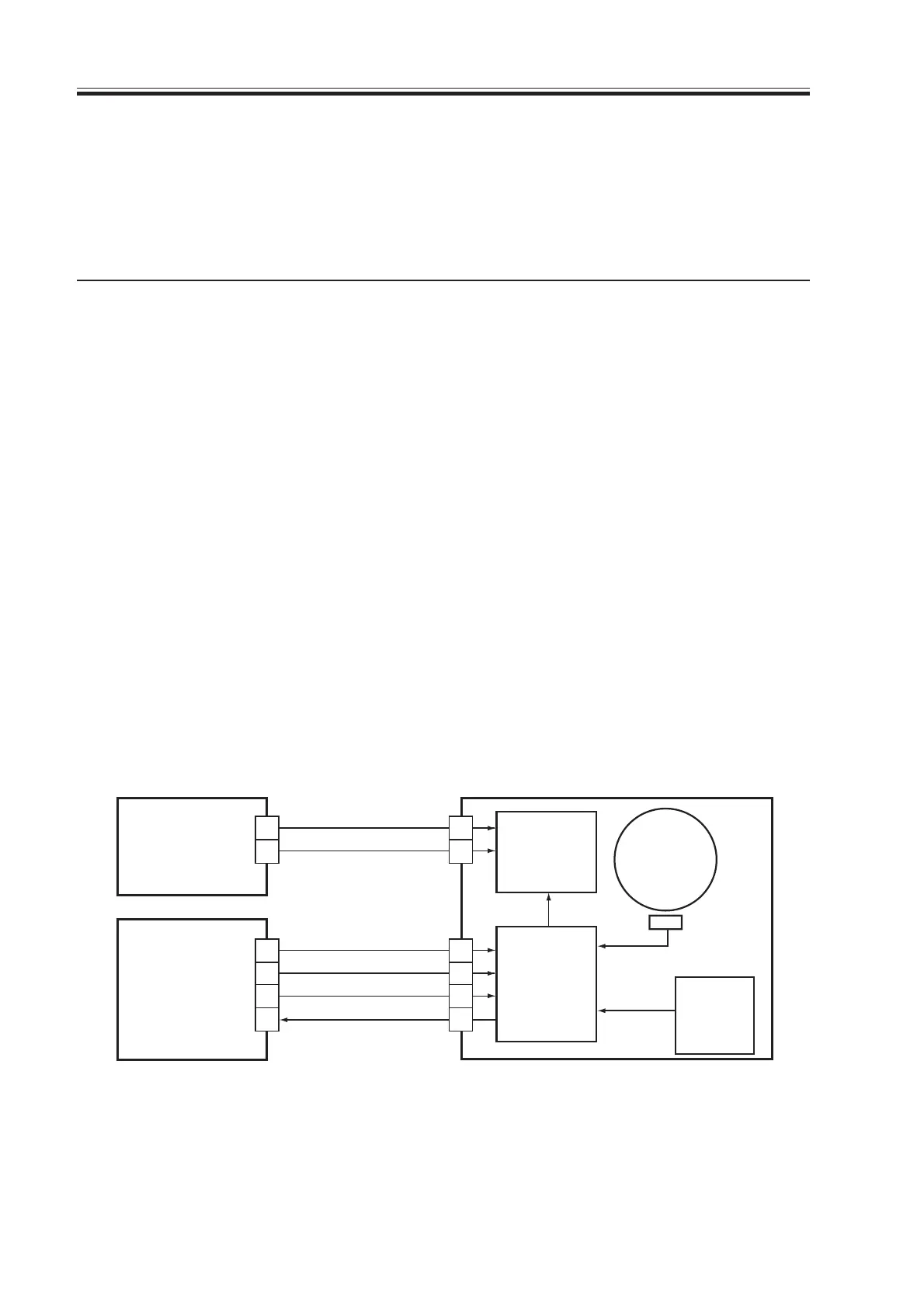
1.4 Controlling the Main Motor (M2)
1.4.1 Outline
The functions of the main motor control circuit are as shown in the following table, and
its block diagram is shown in the following figure:
1. When the main motor drive signal (MMON) goes ‘1’, the main motor starts to rotate.
2. When the main motor rotates, clock pulse signals (MMFG) are generated. If the DC
controller PCB detects an error in clock pulse signals, it will indicate “E010” in the con-
trol panel.
F02-104-01 Control Block Diagram
T02-104-01
Item
Power supply
drive signal
Operating/driving
Control
Error detection
Description
24V is supplied by the DC controller PCB
from the DC controller PCB (MMON)
Waste toner feedscrew
Cleaning assembly
Registration roller
Manual feed pickup assembly
Left deck feed roller 2
Developing assembly unit
Turning on/off the motor
Controlling the motor to a specific speed
code E010
Drive circuit
Control circuit
Reference
signal
generation
circuit
Clock pulse
generation
circuit
J632
J631
J108
J4005
DC controller
PCB
DC power supply
PCB
1
2
1
2
3
4
1
2
A8
A7
A6
A5
24V
5V
0V
GND
MMON
MMFG
Main motor
(M2)
[1]
[2]
Download Free Service Manual at http://printer1.blogspot.com
 Loading...


