COPYRIGHT
©
2000 CANON INC. 2000 2000 2000 2000 CANON iR5000/iR6000 REV.0 JULY 2000
CHAPTER 4 IMAGE FORMATION SYSTEM
4-32 P
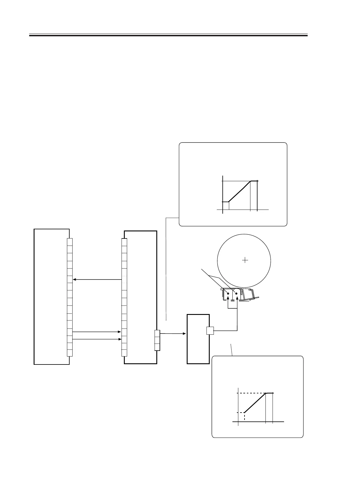
3.6 Controlling Separation Charging
3.6.1 Outline
The system used to control separation charging serves the following functions:
1. Controlling the DC bias to a specific level of current.
2. Controlling the AC bias to a specific level of voltage.
3. Corrects the output to suit the environment and the density of the original used (sur-
face potential of the drum; fuzzy control).
The system used to control separation charging is constructed as follows:
F04-306-01
DC controller PCB
J102A
J4502
AC+DC
J4505
1
2
3
4
5
6
7
8
9
10
11
12
13
14
15
16
1
2
3
4
5
6
7
8
9
10
11
12
13
14
15
16
PT/SP-REMOTE [2]
PT/SP-LEAK-DETECT [1]
SP-CNT [3]
High-voltage PCB
3
2
1
High-voltage
AC transformer
-500µA
The level of current of the DC bias
varies as follows in keeping with
the potential of SP-CNT.
3V
11V 12V
SP-CNT
12KVPP
8KVPP
The level of voltage of the
AC bias varies as follows
in keeping with the potential
of SP-CNT.
3V
11V 12V
HV-CNT
100µA
Separation
charging wire
T4501
Download Free Service Manual at http://printer1.blogspot.com
 Loading...


