COPYRIGHT
©
2000 CANON INC. 2000 2000 2000 2000 CANON iR5000/iR6000 REV.0 JULY 2000
CHAPTER 4 IMAGE FORMATION SYSTEM
4-27 P
3.5 Controlling Transfer Charging
3.5.1 Outline
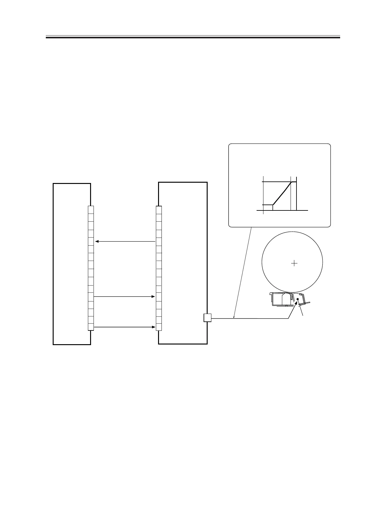
The system used to control transfer charging serves the following functions:
1. Controlling the DC bias to a specific level of current.
2. Controlling the output to suit the environment (fuzzy control).
The following shows the construction of the control system related to the transfer charg-
ing control system.
F04-305-01
The system uses the following signals:
[1] transfer charging leakage detection signal; ‘0’ when an excessively high or low current
is detected.
[2] transfer charging current control signal; when about 3 V or higher and lower than 11 V,
the output of the transfer current turns ON; when about 12 V or higher, it turns OFF.
[3] high-voltage remote signal; turns on/off the transfer current output.
DC controller PCB
High-voltage PCB
J102A
1
2
3
4
5
6
7
8
9
10
11
12
13
14
15
16
TR-CNT [2]
TR-LEAK-DETECT [1]
Transfer
charging wire
T4505
The transfer current varies
as follows in keeping with
the potential of TR-CNT.
1
2
3
4
5
6
7
8
9
10
11
12
13
14
15
16
400µA
3V
11V 12V
TR -CNT
100µA
PR/TR-REMOTE [3]
J4502
Download Free Service Manual at http://printer1.blogspot.com
 Loading...


