COPYRIGHT
©
2000 CANON INC. 2000 2000 2000 2000 CANON iR5000/iR6000 REV.0 JULY 2000
CHAPTER 3 STANDARDS AND ADJUSTMENTS
3-2 T
1.2 Checking the Image Position
Make prints using the following as the source of paper (10 prints each), and check to see
that the image margin and the non-image width are as indicated:
• Each cassette
• Front deck (left, right)
• Manual feed tray
• Duplex feeding unit
• Side paper deck
If not as indicated, adjust the image position in the following order:
1. Adjusting the left/right image margin (registration)
2. Adjusting the image leading edge margin (registration)
3. Adjusting the left/right non-image width (CCD read start position)
4. Leading edge non-image width (scanner image leading edge position)
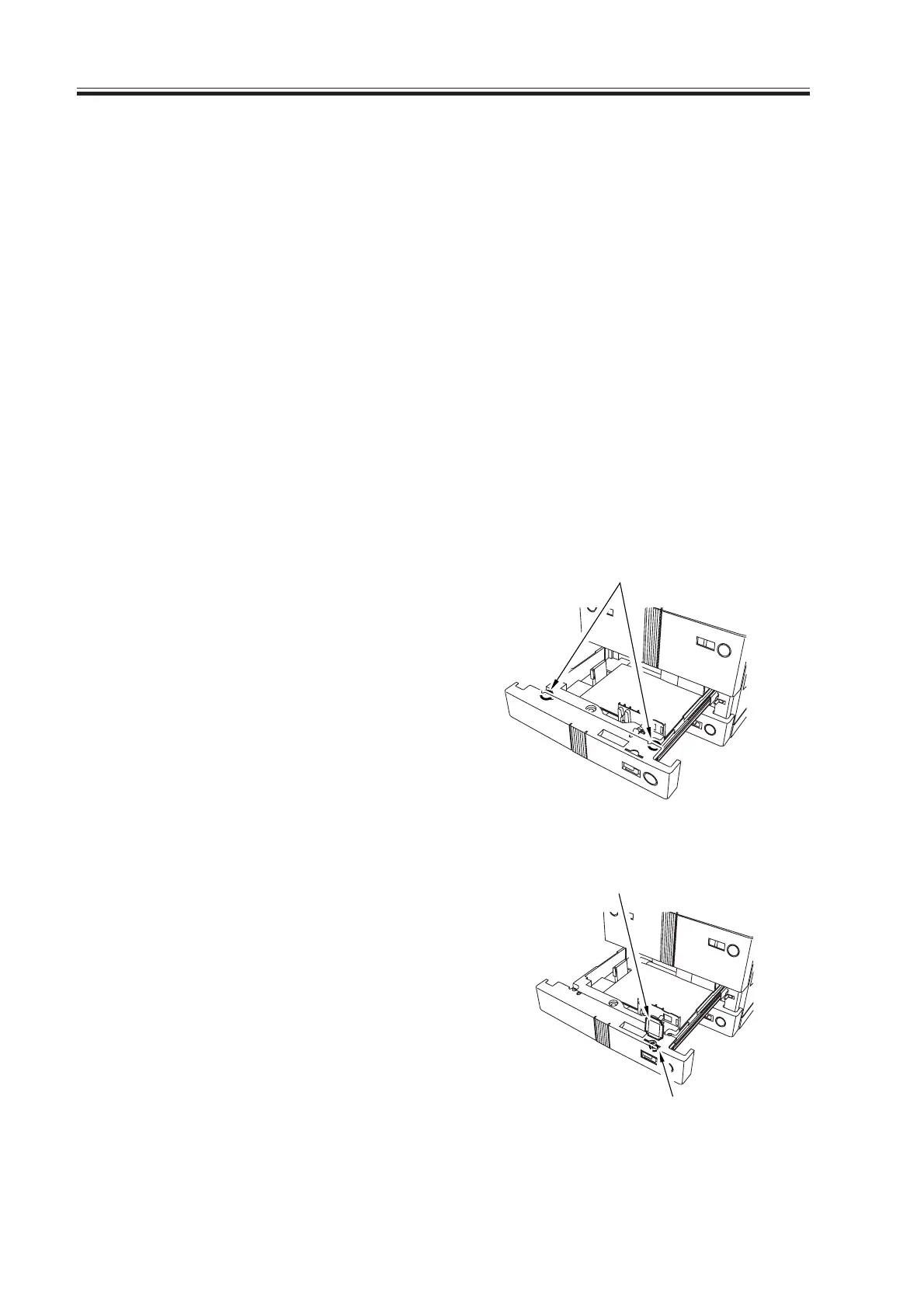
1.3 Adjusting the Left/Right Image Margin
1.3.1 Cassette 3/4
1) Loosen the two fixing screws [1] found
on the left and the right of the cassette.
F03-103-01
2) Remove the paper size plate [2], and
turn the adjusting screw [3] found in the
opening of the paper size plate [2] to
adjust the position; then, tighten the two
fixing screws [1].
After making the adjustment, be sure to
execute the following service mode:
COPIER>FUNCTION>CST>C3-
STMTR/A4R or C4-STMTR/A4R
F03-103-02
[1]
[2]
[3]
Download Free Service Manual at http://printer1.blogspot.com
 Loading...


